
| PLEASE NOTE: The images presented on this page are of low resolution and, as a result, will not print out very well. If you wish to have higher resolution files then you may purchase them for only $2.95 per patent by using the "Buy Now" button below. All purchases are via PayPal. These files have all been cleaned up and digitally enhanced and are therefore suitable for printing, publication or framing. Each zip package contains all the images below (some packages may contain more), and purchased files can be downloaded immediately. |
UNITED STATES PATENT OFFICE.
_________________
CHARLES E. BARLOW, OF PHILADELPHIA, PENNSYLVANIA.
FLOOR-PLANE.
_________________
Specification of Letters Patent No. 19,539, dated March 9, 1858.
_________________
To all whom it may concern:
Be it known that I, CHARLES E. BARLOW, of the city and county of Philadelphia and State of Pennsylvania, have invented a new and useful Improvement in Planes for Planing Decks of Vessels and Boarded Floors; and I do hereby declare that the following is a full and exact description thereof, reference being had to the accompanying drawing, and to the letters of reference marked thereon, making a part of this speciflcation.
The nature of my invention consists in providing an ordinary carpenter’s plane with a frame, so formed and connected as to enable the operator to stand in the most advantageous position while planing the decks of vessels, boarded floors and other similar surfaces.
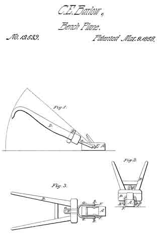
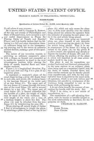
Figure 1 is a longitudinal elevation, Fig. 2 is an end view and F ig. 3 is a plan of my improved plane.
A represents a carpenter’s plane of the usual shape having a pivot (B) firmly fixed to each side, said pivots (B) working freely in the bearings formed on the lower part of an iron frame (C). The upper part of the iron frame (C) passes through the lower stay of the wood frame (D) and is secured thereto by a key (E). The upper part of wood frame (D) is formed somewhat like the handles of a plow, the length of which may be made to suit the workman. The total length of the whole (for a man of a medium height) is about five feet. The plane (A) may be detached from the iron frame (C) by withdrawing the pins (E).
When planing off certain kinds of timber I find it advantageous to weight the plane, by attaching a plate of lead to the top of the (A) to slide more steadily over the article being planed but relieves the operator from the necessity of pressing the said plane (A) on to the said article being planed.
The workman when using my improved plane can place himself in any desirable position without moving the plane (A) from the article being planed. That is to say in consequence of the frame (C) being attached to the plane (A) by the pivots B as above stated-the operator may elevate or depress the handles of frames (D) and (C) without affecting the position of the plane A which will therefore in all cases accommodate itself to the work.
The plane A and its connections are worked backward and forward substantially in the same manner as an ordinary plane when being used on a carpenter’s bench; and the decks of vessels, boarded fioors and other similar surfaces can be thereby planed more expeditiously, and with far less manual labor than is required by the usual mode of operation, which is not only tedious and laborious, but painful in consequence of the workman being compelled to rest on his knees while performing the same.
I do not claim broadly the manner of connecting the handle with the stock. But
What I do claim, as a new article of manufacture, is —
The construction of a self adjusting floor plane, with its handle or handles hinged to the stock substantially as described, for the purposes set forth.
CHARLES E. BARLOW.
Witnesses:
JAMES ECCLES,
JOHNN CLOUDS.