
| PLEASE NOTE: The images presented on this page are of low resolution and, as a result, will not print out very well. If you wish to have higher resolution files then you may purchase them for only $2.95 per patent by using the "Buy Now" button below. All purchases are via PayPal. These files have all been cleaned up and digitally enhanced and are therefore suitable for printing, publication or framing. Each zip package contains all the images below (some packages may contain more), and purchased files can be downloaded immediately. |
UNITED STATES PATENT OFFICE.
_________________
CHARLOTTE SMITH, OF CHELSEA, MASSACHUSETTS, ADMINISTRATRIX OF JOHN F. SMITH, DECEASED.
IMPROVEMENT IN BENCH-PLANES.
_________________
Specification forming part of Letters Patent No. 202,674, dated April 23, 1878; application filed March 26, 1878.
_________________
To all whom it may concern:
Be it known that I, CHARLOTTE SMITH, of Chelsea, Suffolk, State of Massachusetts, administratrix of the estate of my deceased husband, JOHN FRANCIS SMITH, of said city, county, and State, do declare that the said deceased, during his lifetime, did invent a new and useful Plane-Iron Cap, of which the following is a specification:
The nature of the invention is that of a plate of metal of peculiar form, detachable, but when in use fastened by a peculiar device to one side of a plane-iron, being an improvement on the well-known plane-iron top of a carpenter’s plane; and the object of the improvement is to effect the ready removal of the top when required, and also the firmer holding it in place when in use.
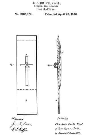
Figure 1 is a view of one side of the plane-iron, showing the nut used to fasten the top, and the necessary slot in the plane-iron, &c. Fig. 2 is a vertical cross-section, giving the relative positions of the plane-iron, the top with its screw, and the nut of the same.
In the drawings, A, Figs. 1 and 2, is the plane-iron or blade of a carpenter’s plane. B, Fig. 1, is a slot in the same, of any convenient length or width, running lengthwise of the plane-iron. C, Figs. 1 and 2, is a nut, with a projection each side of it, (seen in Fig. 1,) forming a thumb-screw, a, being worked by the thumb and finger, screwed onto the screw D, Figs. 1 and 2, which screw passes through the slot B, Fig. 1, as seen in Fig. 2, and at the right-hand side in Fig. 2 is attached to the plane-iron top E, Fig. 2. A shoulder (seen in both figures, in dashed lines in Fig. 2) is attached to the base of the screw D, and also to the top E, and is cut away (see Fig. 1) on each side of the screw D, so as to enter into the slot B.
The inner surface of the top E is seen in Fig. 2 not to lie flat on the plane-iron, but to rest on the same by its ends, which are both, in the same figure, seen to be curved. The thinness of the top E, with the two curves noted, makes of it a spring of greater or less strength, as the thickness of the top E may vary.
It is not proposed to confine ourselves to any particular thickness of the top, nor to any particular curve of the ends. A circular enlargement is sometimes made of the slot B near one or the other end; but this is not claimed here as original.
The length of the shoulder portion left on entering into the slot B may be varied. The whole device of the top and its attachment may be adapted to any plane-iron, the size of the thumb-screw being varied to suit the width of th slot which may be borne by the plane-iron.
Operation: The parts of the device being in place, as seen in the drawings, the nut C is turned by the thumb and finger, thus bending, more or less, the top E and pressing the curved ends more tightly on the plane-iron. When the top E is to be removed there is no loss of time in searching for a screw-driver; but the thumb-screw C is readily turned by the thumb and finger, as before, and the top E is at once loosened; and if the slot B is cut as drawn in Fig. 1, the thumb-screw C is removed, when the top E is readily removed to admit the sharpening of the cutting-edge of the plane-iron.
If the circular enlargement referred to as optionally provided is present, the nut need not be removed, the thumb-screw arms in that case passing through the slot B.
I do not claim the providing the top with a single curved end.
I claim for the inventor —
1. The double curved plane-iron top shown, in combination with the plane-iron, the shoulder, the screw D, and a nut, all when constructed and fitted for use, substantially as described and shown.
2. The combination of the thumb-screw with its arms, the screw D, the shoulder seen, a plane-iron, and a plane-iron top, all when constructed and arranged substantially as described and shown.
CHARLOTTE SMITH,
Admimistratrar of John Francis Smith.
Witnesses:
JOS. B. BELL,
LEMUEL P. JENKS.