| PLEASE NOTE: The images presented on this page are of low resolution and, as a result, will not print out very well. If you wish to have higher resolution files then you may purchase them for only $2.95 per patent by using the "Buy Now" button below. All purchases are via PayPal. These files have all been cleaned up and digitally enhanced and are therefore suitable for printing, publication or framing. Each zip package contains all the images below (some packages may contain more), and purchased files can be downloaded immediately. |
UNITED STATES PATENT OFFICE.
_________________
L. BAILEY, OF WINCHESTER, MASSACHUSETTS.
DEVICE FOR ADJUSTING- PLANE-IRONS.
_________________
Specification of Letters Patent No. 20,615, dated June 22, 1858.
_________________
To all whom it may concern:
Be it known that I, LEONARD BAILEY, of Winchester, in the county of Middlesex and State of Massachusetts, have invented a new and useful Improvement in Joiners’ Planes; and I do hereby declare that the same is fully described and represented in the following specification and the accompanying drawings, of which —
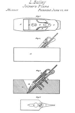
Figure 1, is a top view. Fig. 2, a side elevation; and Fig. 3, a vertical, central and longitudinal section of a plane having my improvement. Fig. 4, is a top view of the friction plate and its adjuster.
The nature of my invention consists in the application of a movable friction plate and a device for adjusting or moving it to the rear side of the throat of a plane stock, and so as to support the plane iron or cutter and be a means by which it may be set or adjusted with respect to the bearing or bottom of the plane stock.
In the drawings, A, denotes the stock of which B, is the throat; C, the plane iron, the latter with its cap iron D, being held in place by a lever E, a thumb cam F, and a bearer or screw, G.
The bearer extends upward from the rear side of the throat and through slots made in the plane iron, the cap iron and the lever and its head serves as a fulcrum to the lever. A spring, H, projecting from the lever as shown in the drawings, serves to separate the thumb cam from the cap in a manner to prevent the former from being turned by the latter while it is being moved longitudinally with the plane iron.
I, is a metallic plate, which is placed fiat against the rear face a, of the throat, B, and serves to support the plane iron. This plate I, is formed with a slot, b, and a circular opening, c, the latter being for the reception of an eccentric, d, projecting from a lever, e, which turns on a fulcrum or screw, f, arranged as shown in the drawings. By turning the lever on its fulcrum in one direction the friction plate, will be raised upward in the throat. So by turning the lever in the opposite way, the plate will be depressed, the amount of movement of the friction plate depending on that of the lever. As the plane iron or cutter rests directly on and is forced down upon the friction plate, it will be moved by and with the latter and so that its cutting edge may be adjusted with great nicety with respect to its distance from or beyond the supporting face or bottom surface of the stock.
The lever, e, the eccentric, d, and the opening c, I term the adjuster, as when applied to the stock and plate, I, as described, they constitute a means of adjusting the plane iron as explained. Were the adjuster applied directly to the plane iron as it is to the friction plate, that is were we to dispense with the friction plate and insert the eccentric of the adjuster in a circular orifice made in the plane iron, it will be readily seen that but very little wear of the plane iron, such as must necessarily take place in sharpening it, or in other words, a reduction of its length, a distance equal to the eccentricity of the eccentric, would render the iron useless. By having a friction plate independent of the plane iron, the extent of grinding or reduction of the plane iron is not limited to the amount of eccentricity of the eccentric, but may be carried on to a much greater extent. Thus, the advantages of my invention will be apparent. It can be applied to most ordinary plane stocks without alteration of the plane iron, or any addition thereto, and it enables the plane iron to be adjusted with great nicety, without requiring the fastening contrivance to be first loosened.
I claim —
The combination of the movable friction plate, I, (separate from the plane iron, C,) and its adjuster or the equivalent of the latter with the throat of the plane stock and to operate the plane iron substantially as specified.
In testimony whereof, I have hereunto set my signature.
LEONARD BAILEY.
Witnesses:
R. N. EDDY,
F. P. HALE, Jr.


