
| PLEASE NOTE: The images presented on this page are of low resolution and, as a result, will not print out very well. If you wish to have higher resolution files then you may purchase them for only $2.95 per patent by using the "Buy Now" button below. All purchases are via PayPal. These files have all been cleaned up and digitally enhanced and are therefore suitable for printing, publication or framing. Each zip package contains all the images below (some packages may contain more), and purchased files can be downloaded immediately. |
UNITED STATES PATENT OFFICE.
_________________
JUSTUS A. TRAUT, OF NEW BRITAIN, CONNECTICUT.
IMPROVEMENT IN BENCH-PLANES.
_________________
Specification forming part of Letters Patent No. 206,507, dated July 30, 1878; application filed June 3, 1878.
_________________
To all whom it may concern:
Be it known that I, JUSTUS A. TRAUT, of New Britain, in the county of Hartford and State of Connecticut, have invented certain new and useful Improvements in Planes, of which the following is a specification:
The invention relates to that class of small planes known as “rounds,” “hollows,” “beading-planes,” &c.; and the invention has for its object the production of this class of planes in iron, whereby they are more durable and as cheap or cheaper than wooden ones, and also to make one or two handles and frames answer for many stocks or for a complete set, whereby they are less expensive and occupy less space for storage than those heretofore made.
My invention consists, first, of a plane handle and frame, having a longitudinal rabbet and provided with clamping mechanism, in combination with a separately-formed plane-stock and its cutter, adapted when united to be readily attached and detached to the side of said frame, as hereinafter described; and, second, in the particular clamping mechanism, as hereinafter described.
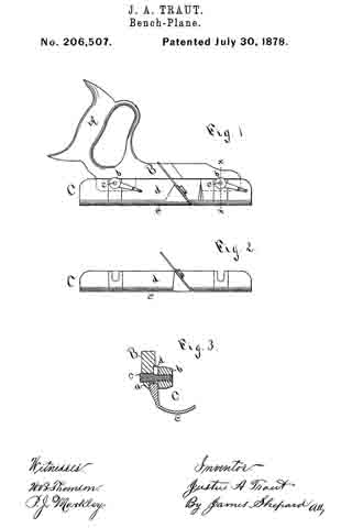
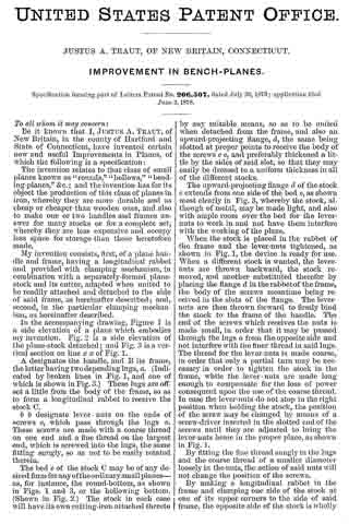
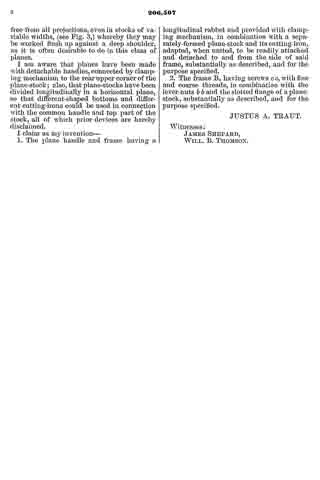
In the accompanying drawing, Figure 1 is a side elevation of a plane which embodies my invention. Fig. 2 is a side elevation of the plane-stock detached; and Fig. 3 is a vertical section on line x x of Fig. 1.
A designates the handle, and B its frame, the latter having two depending lugs, a. (Indicated by broken lines in Fig. 1, and one of which is shown in Fig. 3.) These lugs are off-set a little from the body of the frame, so as to form a longitudinal rabbet to receive the stock C.
b b designate lever-nuts on the ends of screws c, which pass through the lugs a. These screws are made with a coarse thread on one end and a fine thread on the largest end, which is screwed into the lugs, the same fitting snugly, so as not to be easily rotated therein.
The bed e of the stock C may be of any desired form for any of the ordinary small planes — as, for instance, the round-bottom, as shown in Figs. 1 and 3, or the hollowing bottom.
(Shown in Fig. 2.) The stock in each case will have its own cutting-iron attached thereto by any suitable means, so as to be united when detached from the frame, and also an upward-projecting flange, d, the same being slotted at proper points to receive the body of the screws c c, and preferably thickened a little by the sides of said slot, so that they may easily be dressed to a uniform thickness in all of the different stocks.
The upward-projecting flange d of the stock c extends from one side of the bed e, as shown most clearly in Fig. 3. whereby the stock, although of metal, may be made light, and also with ample room over the bed for the lever-nuts to work in and not have them interfere with the working of the plane.
When the stock is placed in the rabbet of the frame and the lever-nuts tightened, as shown in Fig. 1, the device is ready for use. When a different stock is wanted, the lever-nuts are thrown backward, the stock removed, and another substituted therefor by placing the flange d in the rabbet of the frame, the body of the screws meantime being received in the slots of the flange. The lever-nuts are then thrown forward to firmly bind the stock to the frame of the handle. The end of the screws which receives the nuts is made small, in order that it may be passed through the lugs a from the opposite side and not interfere with the finer thread in said lugs. The thread for the lever-nuts is made coarse, in order that only a partial turn may be necessary in order to tighten the stock in the frame, while the lever-nuts are made long enough to compensate for the loss of power consequent upon the use of the coarse thread. In case the lever-nuts do not stop in the right position when holding the stock, the position of the screw may be changed by means of a screw-driver inserted in the slotted end of the screws until they are adjusted to bring the lever-nuts home in the proper place, as shown in Fig. 1.
By fitting the fine thread snugly in the lugs and the coarse thread of a smaller diameter loosely in the nuts, the action of said nuts will not change the position ofthe screws.
By making a longitudinal rabbet in the frame and clamping one side of the stock at one of its upper corners to the side of said frame, the opposite side of the stock is wholly free from all projections, even in stocks of variable widths, (see Fig. 3,) whereby they may be worked flush up against a deep shoulder, as it is often desirable to do in this class of planes.
I am aware that planes have been made with detachable handles, connected by clamping mechanism to the rear upper corner of the plane-stock; also, that plane-stocks have been divided longitudinally in a horizontal plane, so that different-shaped bottoms and different cutting-irons could be used in connection with the common handle and top part of the stock, all of which prior devices are hereby disclaimed.
I claim as my invention —
1. The plane handle and frame having a longitudinal rabbet and provided with clamping mechanism, in combination with a separately-formed plane-stock and its cutting-iron, adapted, when united, to be readily attached and detached to and from the side of said frame, substantially as described, and for the purpose specified.
2. The frame B, having screws c c, with fine and coarse threads, in combination with the lever-nuts b b and the slotted flange of a plane-stock, substantially as described, and for the purpose specified.
JUSTUS A. TRAUT.
Witnesses:
JAMES SHEPARD,
WILL. B. THOMSON.