| PLEASE NOTE: The images presented on this page are of low resolution and, as a result, will not print out very well. If you wish to have higher resolution files then you may purchase them for only $2.95 per patent by using the "Buy Now" button below. All purchases are via PayPal. These files have all been cleaned up and digitally enhanced and are therefore suitable for printing, publication or framing. Each zip package contains all the images below (some packages may contain more), and purchased files can be downloaded immediately. |
UNITED STATES PATENT OFFICE.
_________________
ANDREW JOHNSON, OF CHICAGO, ILLINOIS.
IMPROVEMENT IN PLANES.
_________________
Specification forming part of Letters Patent No. 211,852, dated February 4, 1879; application filed November 14, 1878.
_________________
To all whom it may concern:
Be it known that I, ANDREW JOHNSON, of Chicago, in the county of Cook and State of Illinois, have invented a new and useful Improvement in Planes, of which the following is a specification, reference being had to the accompanying drawings, illustrating my improvement.
The present invention relates to an improvement in joiners’ planes; and the nature of the present invention consists in the novel means for combining the plane bit and stock, whereby a non-slotted bit is held in place by compression of a cap, which is brought with proper force on the bit by means of bolts secured to the sides of the stock. The compressing-plate has side eyes, through which the said bolts pass, and turned onto the bolts are thumb-screws, which may be loosened to move the bit to any desired feed, as the whole is to be hereinafter fully described and shown.
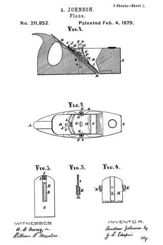
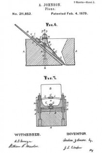
In the drawings, Figure 1 is a longitudinal central section of a smoothing-plane provided with my improvement; Fig. 2, a plan or top view of the same. Fig. 3 is a top view of the bit-cap removed from the other parts. Fig. 4 is an inverted view of the compressing-plate; Fig. 5, an elevation of one of the screw-bolts removed from its position in the stock. Fig. 6 is an enlarged broken central longitudinal section, being an enlargement of the middle portion of Fig. 1; Fig. 7, a transverse section of the plane, taken through x x, also enlarged.
A represents the plane-stock, which has the ordinary construction, and B is an ordinary non-slotted bit, which is fitted on the base of the throat of the stock, as in other planes in the state of the art, there being, however, no key-seats for a wedge.
The cap C is provided with a slot, the margins of which are formed to countersink in the ordinary manner the nut F, which is turned on the screw G, or receives it, that the clamping-plate H and cap C may be rigidly united when required. The upper side of the cap, and surrounding the slot D, is provided with a projection, E, which fits into a recess, L, in the plate H, and insures a true movement of the cap to or from the edge of the bit. The cap C is also provided with notches I on its top side and near its upper end, in which may be inserted a screw-driver or other tool to set the cap from the edge of the bit, the cap being set to the edge of the bit by hammer-blows on the head J.
The plate H is provided with pipe-eyes N N on its sides, which are located so as to pass over screw-bolts O. These bolts are inserted in the margins of the throat of the stock, and the holes in the plane through which they are inserted are plugged.
Thumb-nuts P, turned onto the upper end of the screw-bolts, hold the plate H, cap C, and bit B firmly in the stock.
Rubber pipes or rubber strips R, are placed around the screw-bolts O, for the purpose of raising the cap C from the bit when the thumb-nuts P are loosened, that the bit B may be adjusted, the rubber coming high enough on the bolts to accomplish this purpose by pressing against the under ends of the pipe-eyes N.
By this means non-slotted bits can be used with the advantage of a cap without the objection to the slot, which renders the bit useless when it is worn to the slot, and at the same time the bit C can be removed from or inserted in the throat at the face of the plane, and thus obviate the drilling of the bit by its contact with the cap, as when the bit is inserted in the top of the stock.
I also make plane spoke-shaves on this principle, and they have the same advantages as herein related in reference to the plane; and I also attach my device to planes having other forms and lengths, and they also operate in a superior manner.
I claim as new —
1. The combination of the bit B, cap C, compression-plate H, screw-bolts O, thumb-nuts P, and stock A, as and for the purpose set forth.
2. The rubber R, in combination with bolts O, stock A, thumb-nuts P, bit B, cap C, and plate H, provided with eyes N, as and for the purpose described.
ANDREW JOHNSON.
Witnesses:
A. G. MOREY,
G. L. CHAPIN.


