

| PLEASE NOTE: The images presented on this page are of low resolution and, as a result, will not print out very well. If you wish to have higher resolution files then you may purchase them for only $2.95 per patent by using the "Buy Now" button below. All purchases are via PayPal. These files have all been cleaned up and digitally enhanced and are therefore suitable for printing, publication or framing. Each zip package contains all the images below (some packages may contain more), and purchased files can be downloaded immediately. |
UNITED STATES PATENT OFFICE.
_________________
WILLIAM STEERS, OF SHERBBOOKE, QUEBEC, CANADA.
BENCH-PLANE.
_________________
SPECIFICATION forming part of Letters Patent No. 227,452, dated May 11, 1880.
Application filed February 2, 1880.
_________________
To all whom it may concern:
Be it known that I, WILLIAM STEERS, of the city of Sherbrooke, in the Province of Quebec, in the Dominion of Canada, have invented new and useful Improvements in Metallic Planes, which improvements are fully set forth in the following specification, reference being had to the accompanying drawing.
The first part of my invention relates to the device by which the knife or “iron” is adjusted to various inclinations and secured in any position to suit the various degrees of hardness and grain of the different kinds of wood on which it may be used. The second part relates to the device by which the “cap ” or “back-iron” is adjusted to suit the required angle of the knife, and at the same time the back-iron serves in place of both holder and of back-iron or cap as ordinarily used; and, thirdly, to the device by which the knife is regulated to project from the face ofthe plane.
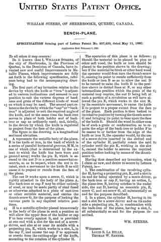
The figure in the drawing is a longitudinal sectional elevation.
A represents the metallic body of the plane. B is the knife or iron, in the back of which is a series of parallel horizontal grooves, M M, in one of which (that is determined by the extent to which the knife has been worn and ground away) works the pin E, which is secured to the nut D in a position somewhat eccentric, so as to impart, when the nut is rotated, such a movement to the knife B as will cause it to project or recede from the face of the plane.
The nut D works upon a screw, C, which is rigidly attached to the body of the plane A. The back-iron or cap F may be either entirely of steel, or may be made partly of steel fused or otherwise attached to a plate of cast-iron or other suitable material, and carries the thumb-screw G, for the purpose of locking the various parts in any required relative positions.
H is a metallic cylinder placed transversely to the body of the plane in such a position as will allow the upper face of the holder or cap F to bear evenly against it, and is provided at one end with a slot for the end of a screw-driver, and also at or near its middle with a projecting pin, K, which works in a slot, L, in the cap F, and causes the cap F to approach or recede from the cutting-edge of the knife, according to the rotation of the cylinder H.
The operation of this plane is as follows: Should the material to be planed be pine or other soft wood, the knife or iron should be placed in the position shown in the drawing; but if the material be birch or other hard wood the operator would first turn the thumb-screw G, causing its point to recede sufficiently from the knife or iron B so as to allow the nut D to be turned to raise the knife B to the position shown in dotted lines at N, or any other intermediate position which the grain of the material may require, the nut D being left at such a portion of a revolution as will have allowed the pin E, which works in the slot M, by its eccentric movement, to cause the knife B to project to a proper extent from the face of the plane. Each portion is then locked in its relative position by turning the thumb-screw G and bringing its point to bear upon the face of the knife B. Should the wood in either case be of such a grain or conformation as to require the edge of the back-iron or holder F to be nearer to or farther from the edge of the knife or iron B, the operator would, by the use of a screw-driver inserted in the slotted end of the cylinder H, partially rotate the said cylinder until the pin K, working in the slot L, caused the holder to assume the required position before locking by means ofthe thumb-screw G.
Having thus described my invention, what I claim as new, and desire to secure by Letters Patent, is —
1. The combination of the revolving cylinder H, having a projecting pin, K, and a slot in its end for being operated by a screw-driver, the back-iron or cap F, having an orifice, L, the plane-iron B, having notches in the under side, the nut D, having an eccentric pin, E, screw C, and set-screw G, all substantially as and for the purpose described.
2. In a plane, the cylinder H, having in its end a slot for a screw-driver and on its under side a projecting pin, K, in combination with the back-iron of the plane, having a slot, L, all substantially as and for the purpose described.
WM. STEERS.
Witnesses:
LOUIS S. LA BILLE,
THOMAS W. SANNER.