

| PLEASE NOTE: The images presented on this page are of low resolution and, as a result, will not print out very well. If you wish to have higher resolution files then you may purchase them for only $2.95 per patent by using the "Buy Now" button below. All purchases are via PayPal. These files have all been cleaned up and digitally enhanced and are therefore suitable for printing, publication or framing. Each zip package contains all the images below (some packages may contain more), and purchased files can be downloaded immediately. |
UNITED STATES PATENT OFFICE.
_________________
CYRUS KINNEY, OF WINDSOR, ONTARIO, CANADA.
BENCH-PLANE GAGE.
_________________
SPECIFICATION forming part of Letters Patent No. 228,766, dated June 15, 1880.
Application filed April 15, 1880. (No model.)
_________________
To all whom it may concern:
Be it known that I, CYRUS KINNEY, of Windsor, Essex county, Province of Ontario, Canada, have invented an Improvement in Bench-Plane Gages, of which the following is a specification.
My invention relates to that class of gages for bench-planes which is specially adapted to be used when squaring or beveling the material; and the invention consists in the peculiar construction and arrangement of parts, as hereinafter more fully described, and then pointed out in the claims.
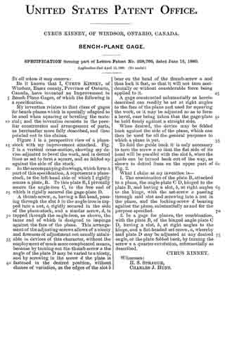
Figure 1 is a perspective view of a plane-stock with my improvement attached. Fig 2 is a vertical cross-section, showing my device adjusted to bevel the work, and in dotted lines as set to form a square, and as folded up against the side of the stock.
In the accompanying drawings, which form a part of this specification, A represents a plane-stock, to the left-hand side of which I rigidly secure a plate, B. To this plate B, I pivotally secure the angle-iron C, to the free end of which is rigidly secured the gage-plate D.
A thumb-screw, a, having a flat head, passing through the slot b in the angle-iron is tapped into a nut, c, rigidly secured in the side of the plane-stock, and a similar screw, d, is tapped through the angle-iron, as shown, the inner end of which is designed to impinge against the face of the plane. This arrangement of the adjusting-screws allows of a nicety and firmness of adjustment not usually attainable in devices of this character, without the employment of much more complicated means, because by turning out the thumb-screw a the angle of the plate D may be varied to a nicety, and by screwing in the screw d the plate is fastened in the desired position, without chance of variation, as the edges of the slot b bear on the head of the thumb-screw a and thus lock it fast, so that it will not turn accidentally or without considerable force being applied to it.
A gage constructed substantially as herein described can readily be set at right angles to the face of the plane and used for squaring the work, or it may be adjusted so as to form a bevel, care being taken that the gage-plate be held firmly against a straight side.
When desired, the device may be folded back against the side of the plane, which can then be used for all the general purposes to which a plane is put.
To fold the guide back it is only necessary to turn the screw a so that the flat side of its head will be parallel with the slot b, when the guide can be turned back out of the way, as shown in dotted lines on the upper part of Fig. 2.
What I claim as my invention is —
1. The combination of the plate B, attached to a plane, the angle-plate C D, hinged to the plate B, and having a slot, b, at right angles to the hinge, with the set-screw a passing through said slot and screwing into a nut in the plane, and the locking-screw ol bearing against the plane, substantially as and for the purpose specified.
2. In a gage for planes, the combination, with the plate B, of the hinged angle-plate C D, having a slot, b, at right angles to the hinge, and a flat-headed set-screw, a, whereby said plate D may be adjusted at any desired angle, or the plate folded back, by turning the screw a a quarter-revolution, substantially as described.
CYRUS KINNEY.
Witnesses:
H. S. SPRAGUE,
CHARLES J. HUNT.