

| PLEASE NOTE: The images presented on this page are of low resolution and, as a result, will not print out very well. If you wish to have higher resolution files then you may purchase them for only $2.95 per patent by using the "Buy Now" button below. All purchases are via PayPal. These files have all been cleaned up and digitally enhanced and are therefore suitable for printing, publication or framing. Each zip package contains all the images below (some packages may contain more), and purchased files can be downloaded immediately. |
UNITED STATES PATENT OFFICE.
_________________
FREDERIC KRAENGEL, OF BUFFALO, NEW YORK, ASSIGNOR OF ONE-HALF OF HIS RIGHT TO EMIL JETTER AND ALBERT JETTER, OF SAME PLACE.
BENCH-PLANE.
_________________
SPECIFICATION forming part of Letters Patent No. 231,331, dated August 17, 1880.
Application filed April 30, 1880. (No model.)
_________________
To all whom it may concern:
Be it known that I, FREDERIC KRAENGEL, of Buftalo, in the county of Erie and State of New York, have invented certain new and useful Improvements on a Bench-Plane; and I do hereby declare that the following description of my said invention, taken in connection with the accompanying sheet of drawings, forms a full, clear, and exact specification, which will enable others skilled in the art to which it appertains to make and use the same.
This invention has general reference to planes; and it consists in certain peculiar combination of parts and details of construction whereby the plane iron or irons are rendered adjustable, and the throat of the plane-stock enlarged or diminished, substantially in a manner as hereinafter first fully set forth and described, and then pointed out in the claims.
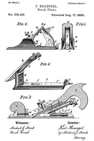
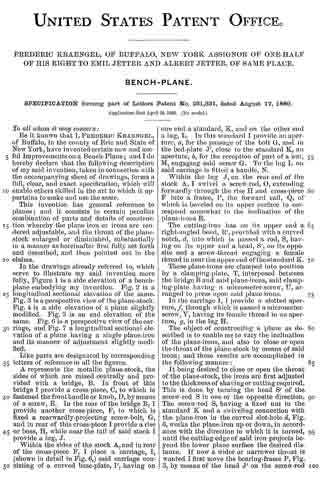
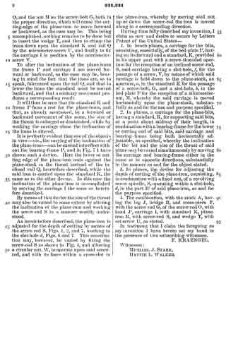
In the drawings already referred to, which serve to illustrate my said invention more fully, Figure 1 is a side elevation of a bench-plane embodying my invention. Fig. 2 is a longitudinal sectional elevation of the same. Fig. 3 is a perspective view of the plane-stock. Fig. 4. is a side elevation of a plane slightly modified. Fig. 5 is an end elevation of the same. Fig. 6 is a perspective view of the carriage, and Fig. 7 a longitudinal sectional elevation of a plane having a single plane-iron and its manner of adjustment slightly modified.
Like parts are designated by corresponding letters of reference in all the figures.
A represents the metallic plane-stock, the sides of which are raised centrally and provided with a bridge, B. In front of this bridge I provide a cross-piece, C, to which is fastened the front handle or knob, D, by means of a screw, E. In the rear of the bridge B, I provide another cross-piece, F, to which is fixed a rearwardly-projecting screw-bolt, G, and in rear of this cross-piece I provide a rise or boss, H, while near the tail of said stock I provide a lug, J.
Within the sides of the stock A, and in rear of the cross-piece F, I place a carriage, I, (shown in detail in Fig. 6,) said carriage consisting of a curved base-plate, I’, having on one end a standard, K, and on the other end a lug, L. In this standard I provide an aperture, a, for the passage of the bolt G, and in the bed-plate J’, close to the standard K, an aperture, b, for the reception of part of a nut, M, engaging said screw G. To the lug L on said carriage is fitted a handle, N.
Within the lug J, on the rear end of the stock A, I swivel a screw-rod, O, extending forwardly through the rise H and cross-piece F into a frame, l’, the forward rail, Q, of which is beveled on its upper surface to correspond somewhat to the inclination ofthe plane-irons R.
The cutting-iron has on its upper end a right-angled bend, R’, provided with a curved notch, d, into which is passed a rod, S, having on its upper end a head, S’, on its opposite end a screw-thread engaging a female thread in near the upper end of the standard K.
These plane-irons are clamped into position by a clamping-plate, T, interposed between the bridge B and said plane-irons, said clamping~plate having a micrometer-screw, U, arranged to press upon said plane-irons.
In the carriage I, I provide a slotted aperture, f, through which is passed a micrometer-screw, V, having its female thread in an aperture, g, in the lug H.
The object of constructing a plane as described is to enable me to vary the inclination of the plane-irons, and also to close or open the throat of the plane-stock by means of said irons, and these results are accomplished in the following manner:
It being desired to close or open the throat of the plane-stock, the irons are first adjusted to the thickness of shaving or cutting required. This is done by turning the head S’ of the screw-rod S in one or the opposite direction. The screw-rod S, having a fixed nut in the standard K and a swiveling connection with the plane-iron in the curved slot-hole d, Fig. 6, works the plane-iron up or down, in accordance with the direction in which it is turned, until the cutting-edge of said iron projects beyond the lower plane surface the desired distance. lf now a wider or narrower throat is wanted I first move the bearing-frame P, Fig. 3, by means of the head J’ on the screw-rod O, and the nut M on the screw-bolt G, both in the proper direction, which will cause the cutting-edge of the plane-iron to move forward or backward, as the case may be. This being accomplished, nothing remains to be done but to insert the wedge T, and then to clamp the irons down upon the standard K and rail Q by the micrometer-screw U, and finally to fix the carriage I in position by the micrometer-screw V.
To alter the inclination of the plane-irons the frame P and carriage I are moved forward or backward, as the case may be, bearing in mind the fact that the irons are, so to speak, fulcrumed upon the rail Q, and that to lower the irons the standard must be moved backward, and that a contrary movement produces a corresponding result.
It will thus be seen that the standard K and frame P form a rest for the plane-irons, and that, as already mentioned, by a forward or backward movement of the same, the size of the throat is enlarged or diminished, while by working the carriage alone the inclination of the irons is altered.
It is perfectly evident that one of the objects in view — viz., the varying of the inclination of the plane-irons — can be carried into effect without the bearing-frame P, and in Fig. 7 I have shown such a device. Here the lower or cutting edge of the plane-iron rests against the plane-stock in the throat instead of the inclined rail Q, heretofore described, while the said iron is carried upon the standard K, the same as in the other device. In this case the inclination of the plane-iron is accomplished by moving the carriage I the same as heretofore described.
By means of this device the size of the throat may also be varied to some extent by altering the inclination of the plane-iron and working the screw-rod S in a manner readily understood.
As hereinbefore described, the plane-iron is adjusted for the depth of cutting by means of the screw-rod S, Figs. 1, 2, and 7, working in the slot-hole d, Figs. 6 and 7. This construction may, however, be varied by fixing the screw-rod S as shown in Fig. 4, and allowing a circular nut, W, to operate upon said screw-rod, and with its faces within a cross-slot in the plane-iron, whereby by moving said nut up or down the screw-rod the iron is moved along in a corresponding direction.
Having thus fully described my invention, I claim as new and desire to secure by Letters Patent of the United States —
1. In bench-planes, a carriage for the bits, consisting, essentially, of the bed~plate I’, having on its forward end a standard, K, provided in its upper part with a screw-threaded aperture for the reception of an inclined screw-rod, S, said carriage having a slot-hole, f, for the passage ofa screw, V, by means of which said carriage is held down to the plane-stock, an aperture, a, in the standard K for the passage of a screw-bolt, G, and a slot-hole, b, in the bed-plate I’ for the reception of a micrometer-nut, M, whereby the said carriage is moved horizontally upon the plane-stock, substantially as and for the use and purpose specified.
2. In planes, a carriage for the plane-bits, having a standard, K, for supporting said bits, at a point about midway of their length, in combination with a bearing-frame for the lower or cutting end of said bits, said carriage and bearing-frame being both horizontally adjustable, as specified, whereby the inclination of the bit and the size of the throat of said plane may be varied simultaneously by moving the carriage and bearing-frame either in the same or in opposite directions, substantially in the manner as and for the object stated.
3. In planes, the device for adjusting the depth of cutting of the plane-iron, consisting, in combination with a fixed nut, of a revolving screw-spindle, S, operating within a slot-hole, d, in the part R’ of said plane-iron, as and for the purpose specified.
4. The combination, with the stock A, having the lug J, bridge B, and cross-piece F, with the screw-rod G, of the screw-rod O, with head J’, carriage I, with standard K, plane-iron R, with screw-rod S, and wedge T, with set-screw U, as stated.
In testimony that I claim the foregoing as my invention I have hereto set my hand in the presence of two subscribing witnesses.
F. KRAENGEL.
Witnesses:
MICHAEL J. STARK,
HATTIE L. WALKER.