| PLEASE NOTE: The images presented on this page are of low resolution and, as a result, will not print out very well. If you wish to have higher resolution files then you may purchase them for only $2.95 per patent by using the "Buy Now" button below. All purchases are via PayPal. These files have all been cleaned up and digitally enhanced and are therefore suitable for printing, publication or framing. Each zip package contains all the images below (some packages may contain more), and purchased files can be downloaded immediately. |
UNITED STATES PATENT OFFICE.
_________________
AUGUST P. J. BOSSEL, OF VIRGINIA CITY, NEVADA.
BENCH-PLANE.
_________________
SPECIFICATION forming part of Letters Patent No. 231,990, dated September 7, 1880.
Application filed June 29, 1880. (No model.)
_________________
To all whom it may concern:
Be it known that I. AUGUST P. J. BOSSEL, of Virginia City, in the county of Storey and State of Nevada, have invented a new and useful Improvement in Planes, of which the following is a specification.
My invention is more particularly intended for planes used in rabbeting, but it is applicable to planes of various kinds.
The invention consists, first, in a novel construction, arrangement, and combination, with the plane-bit, of a toothed plate or rack, and a pinion for adjusting the bit, and a wedge for holding it when adjusted; and, further, in a novel arrangement of the handle of the plane and devices connected therewith for adjusting said handle at different positions.
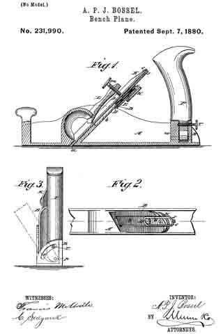
In the accompanying drawings, Figure 1 is a longitudinal vertical section of a plane embodying my irnprovements. Fig. 2 is a top view of a portion of the same with the bit and wedge removed. Fig. 3 is a rear-end view.
Similar letters of reference indicate corresponding parts.
The plane A is preferably made of metal, and the throat a may be of the usual description. At the top of the throat a, is an upwardly-projecting lug or plate, B, in which is journaled a short shaft, the front end of which carries a pinion, D. The rear end of this shaft may have a milled knob attached directly to it, but as here represented it carries a gear-wheel, E, with which engages another gear-wheel, G, carried by one end of a short shaft journaled in said plate B, and having at its other end a milled knob, H.
ln a recess, b, on the front side of the plate B, works a sliding rack, J, with which the pinion D engages. Near the upper end of the rack J, and on the front side thereof, is a projecting pin or stud, s, which engages with a hole in the plane-bit K, near the upper end thereof. By turning the pinion D in one direction or the other the bit K is adjusted up or down in order to regulate its cut.
The wedge L is provided with a thumb-screw, m, which passes through it and bears against the front surface of the bit K. When the bit has been adjusted to the desired position the screw m is tightened so as to hold the bit firnily in place by the combined pressure of said screw and of the lower end or point of the wedge. By the means above described the bit may be readily adjusted with exact nicety without the use of a hannner, as in the ordinary plane.
The handle P, instead of being rigidly attached to the plane, is pivoted at p between a quadrantal plate R, extending upward from the plane near the rear end thereof, and a lug, u’, in front of said plate R.
A thumb-screw, T, passes through an arc-shaped slot, v, in the plate R, and through the handle P above the pivot p, and bears against the lug w, and thus holds the handle firmly in position. When the plane is used in a corner or near a surface where space tor the handle and the hand is limited the handle P may be inclined, as indicated in dotted lines in Fig. 3, and held firmly in position by the screw T.
Having thus described my invention, what I claim as new, and desire to secure by Letters Patent, is —
1. A plane consisting of the body A, provided with the upwardly-extending plate B, having the recess b, the rack J, sliding in said recess, the bit K, having its shank elongated and connected to said rack by the pin or stud s, the pinion D, operating said rack, and the wedge L, provided with the thumb-screw m, substantially as herein described.
2. The handle P, pivoted at p, the are-slotted plate R, and the lug w, in combination with the thumb-screw T, as and for the purpose specified.
AUGUST P. J. BOSSEL.
Witnesses:
D. J. MACINTOSH,
W. COYNE.


