| PLEASE NOTE: The images presented on this page are of low resolution and, as a result, will not print out very well. If you wish to have higher resolution files then you may purchase them for only $2.95 per patent by using the "Buy Now" button below. All purchases are via PayPal. These files have all been cleaned up and digitally enhanced and are therefore suitable for printing, publication or framing. Each zip package contains all the images below (some packages may contain more), and purchased files can be downloaded immediately. |
UNITED STATES PATENT OFFICE.
_________________
W. S. LOUGHBOROUGH, OF ROCHESTER, NEW YORK.
IMPROVED BENCH-PLANE.
_________________
Specification forming part of Letters Patent No. 23,928, dated May 3, 1859.
_________________
To all whom it may concern:
Be it known that I, WM. S. LOUGHBOROUGH, of Rochester, in the county of Monroe and State of New York, have invented a new and useful Iron Fillister-Plane, the principles of which are applicable, with slight modifications, to panel-plows, match-planes, dados, rabbets, and to bench-planes; and I do hereby declare that the following is a full and exact description of its construction and operation, reference being had to the accompanying drawings, and to the letters of reference marked thereon.
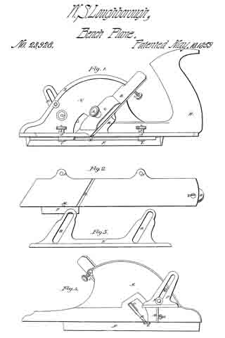
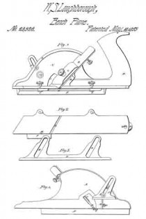
Figure 1 is a side elevation. Fig. 2 is a plan of the race. Fig. 3 is a plan of the parallel fence F. Fig. 4 is an elevation ofthe reverse side of Fig. 1 without the handle, and showing the shape and position of the stop P, also of the spur M.
The nature of my invention consists, first, in the construction of an iron stock for fillisters, dados, rabbets, rnatch-planes, and panel-plows; second, in the construction of a parallel fence, F, for fillisters and match-planes; third, in the construction and arrangement of a stop, P, moving diagonally to the line of pressure upon it, the same being applicable to the dado and panchplow; fourth, in the application and arrangement of the spring-cap G, in combination with the screw 2 or any other adjustable or lined fulcrum; fifth, the combination of the adjusting-screw 1 with the bit B and spring-cap C; sixth, the application and arrangement of the spur M.
I construct the plane-stocks, as seen in Figs. 1 and 4, with an arch, N, which connects the face in front of the throat with that in the rear, and at the same time affording a cutting-edge to the bit B the full width of the face of the plane. The projection R governs the position of the bit. The screw 2 passes through the slot of the bit and into this projection, and the adjusting-screw 1 screws through the said projection and against the upper end of the bit B, so that by turning the said adjusting-screw up the edge of the bit is thrown below the face of the plane, causing it to cut a thicker shaving, and vice versa, whereby the operator is enabled to adjust the “cut” of the bit to the rnerest fraction, and in an instant.
The parallel fence F, I construct, as seen in Fig. 3, with the slots D, through which the screws Y pass, running out from the face of the fence at an angle of sixty degrees, more or less, so that when the nuts 4 and 5 are loosened to make changes one measurement only is required, for neither end can move up or back faster than the other when the screws Y are properly tilted to the slots D.
The stop P is made and arranged, as seen in Fig. 4, with the slot for the set-screw K, in this also running up diagonally from its face, so as to prevent any possibility of the downward pressure of the plane when it has worked to the desired depth from forcing the stop up, and thereby allow it to work too deep. It is kept in its proper position by the guide-pin U.
The handle H is cut to lit under the projection R, and the screw 7, Fig. 2, is put through the face of the plane and into the handle, which holds it firmly to its place.
The spur M, Figs. 2 and 4, is made of plate-steel and fitted into a dovetail seat, where it is held by the screw 6, which has a bevel or a countersunk head, one side of which is pressed against the spur when the screw is turned in.
The projections J are to allow the fence to be adjusted to the full width of the face of the plane. The rib X is to strengthen the arch N.
There may be a slip, V, of wood let into the fence F to prevent the edge of the bit from coming in contact with the iron when the bit is being taken out or replaced.
What I claim as my invention is —
1. The combination of the screw 2, (which takes effect in the projection R,) spring or yielding cap C, bit B, and screw 1, for the purpose of varying the cut of the bit, and at the same time and proportionally the space of the throat, the base of the bit B being the fulcrum upon which it swings when said changes are made, the said combination being applicable for the adjustment of the bit in all kinds of planes.
2. The adjustable parallel fence F, constructed with diagonal slots D for the set-screws Y, as and for the purpose specified, said fence being applicable to match-planes, and also the stop P, with the slot running up diagonally from the face, the set-screw K, and the guide-pin U keeping it in position, said stop being applicable to panel-plows and dados.
WM. S. LOUGHBOROUGH.
Witnesses:
CHARLES GILBERT,
RICHARD GILBERT.


