
| PLEASE NOTE: The images presented on this page are of low resolution and, as a result, will not print out very well. If you wish to have higher resolution files then you may purchase them for only $2.95 per patent by using the "Buy Now" button below. All purchases are via PayPal. These files have all been cleaned up and digitally enhanced and are therefore suitable for printing, publication or framing. Each zip package contains all the images below (some packages may contain more), and purchased files can be downloaded immediately. |

UNITED STATES PATENT OFFICE.
_________________
LEONARD BAILEY, OF HARTFORD, CONNECTICUT.
FLEXIBLE-FACED PLANE.
_________________
SPECIFICATION forming part of Letters Patent No. 242,740, dated June 14, 1881.
Application filed November 13, 1880. (No model.)
_________________
To all whom it may concern:
Beit known that I, LEONARD BAILEY, of Hartford, in the State of Connecticut, have invented certain Improvements in Flexible-Faced Planes, of which the following is a specification.
My invention relates to that class of planes in which the face is made flexible, so that by means of a screw or equivalent device it may be adapted to concave or convex surfaces of different degrees of curvature; and it consists in improvements upon these planes, as now constructed, in four particulars.
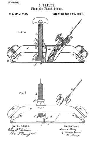
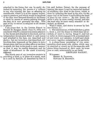
In the drawings, I have shown in Figure 1 a side elevation of a plane embodying my improvements, and in Fig. 2 a longitudinal section of the same.
The first part of my invention relates to the screw for regulating the degree of curvature of the face, and more especially to the method of attaching it to the stock, so that it shall be capable of adjustment in case of wear by use.
In the Letters Patent to Charles H. Sawyer dated April 16, 1867, numbered 63,948, is described a screw passing through the center of the handle or stock, and attached to a piece which is rigidly fastened to the upper surface of the face, by means of which screw the curvature of the face is regulated. It is a matter of great importance in tools of this character that the adjusting-screw should be firmly fixed at the base and yet be permitted to turn freely. When, however, the base of the screw attached to the face, or to a piece of metal affixed to the face, becomes worn, which will happen after the tool has been used for a while, it ceases to be firmly held and becomes loose, and consequently more or less unfitted for use, or altogether useless. It is very desirable, therefore, to provide such means for adjusting the screw, in case of wear, as will overcome this difticulty. In the Sawyer patent referred to no means are provided to overcome the difficulty. I accomplish this very important object by the first part of my invention and in the following way: In the forward part of the stock a is a place for the reception of the base b’ of the screw b, which is somewhat larger in diameter than the main part of the screw. Upon the screw, below the piece c, is placed the nut d, which is of the same diameter as the base b’, and adapted to slide up and down the main part of the screw b. This nut d is fitted with screw-threads, which fit into screw-threads inside the place provided in the stock a for the reception of the base b’ of the screw. Around the periphery of this nut d are countersunk places d’ d’. When the base b’ of the screw b is placed inside of the place in the stock provided for its reception the nut d is to be screwed down and into this place. By this means the screw b is held firmly, and yet may be readily turned. When the screw becomes loose by reason of wear occasioned by use it may be readily tightened by screwing down the nut d sufficiently to accomplish this object. This may be done by means of the countersunk places d’ d’, in which any suitable tool may be inserted to turn the nut d. The screw b passes through the piece c, within which are screw-threads, with which the screw b engages. This piece is fastened to the frame e. Above this piece is the nut f, which travels along the screw b, the office of which is to assist in holding the screw b at any desired point. This is accomplished by screwing the nut f down to the piece c.
The second part of my invention relates to the frame to which the flexible face is attached, (marked e in the drawings,) and consists in making it of two pieces instead of one, as is now the case. This change will be found to be an important one in respect of ease and economy in manufacture, for instead of casting the entire frame in one piece, as is necessary in case of planes as they are now made, the two parts may be struck out of sheet metal and bent into the proper shape. These two pieces are united by the pins h h, with the rods i i connecting the frame e with the flexible face j, the rods turning upon the pins k k, by which they are attached to the face. Just above the rods i i are placed the handles m m, held in place by the screws n n.
The third part of my invention consists of a device for detaching the face from the stock when desired without injury to the former; and consists of the plate o, to which the face is permanently riveted, and which is connected with the stock a by means of two screws, o’ o’, passing through the stock and into but not through the plate o. Through this plate o and the face pass the cutting-irons p p. By the use of this device the face is rigidly attached to the frame, but can be easily detached by removing the screws o’ o’ without in any way injuring the face or affecting its smoothness, which it is of the utmost importance to preserve, and which would be impaired if the face were fastened directly to the frame or stock by means of screws passing through the face, as is now generally the case. This part of my invention is adapted to all classes of planes.
I am aware that in the Letters Patent to Samuel D. Sargent, dated June 17, 1879, and numbered 216,577, a transverse recess adjacent to the throat and attached to the stock, and an independent throat-piece fitted to said recess and attached to the face, are described and shown; but my invention, just described, differs from that, inasmuch as the plate o is not a throat-piece, and has no other office or use than to attach the face to the stock in such manner as that it may be readily detached, and its mode of attachment to the stock is entirely different.
The fourth part of my invention consists in providing a head, q, in place of a crank, such as is used by Sawyer, as described by him in his said Letters Patent, for the purpose of turning the screw b, and an improved method of attaching this head to the screw, which is done by inserting the head in the slot r in the upper end of the screw b and holding the head in place by the screw s. By this means the screw b may be more readily turned, and also the head may be more easily attached or detached, as desired.
What I claim, and desire to secure by Letters Patent, is —
1. The combination, with flexible face j, piece c, stock a, and the frame to which they are attached, of screw b, having flange b’, and nut or collar d, which engages with a recessed part of said stock and operates to hold said stock and screw together, substantially as set forth.
2. A plane-frame consisting of two corresponding sheet-metal side plates, which may be stamped or struck up by the same die, said plates being fastened at their ends by cross pins or rods, substantially as set forth.
LEONARD BAILEY.
Witnesses:
HENRY E. TAINTOR,
EDWARD B. BENNETT.