
| PLEASE NOTE: The images presented on this page are of low resolution and, as a result, will not print out very well. If you wish to have higher resolution files then you may purchase them for only $2.95 per patent by using the "Buy Now" button below. All purchases are via PayPal. These files have all been cleaned up and digitally enhanced and are therefore suitable for printing, publication or framing. Each zip package contains all the images below (some packages may contain more), and purchased files can be downloaded immediately. |
UNITED STATES PATENT OFFICE.
_________________
REUBEN FRETZ, OF MONTVILLE TOWNSHIP, OHIO.
MACHINE FOR FINISHING THE EXTERIOR OF RIMS OF CARRIAGE-WHEELS.
_________________
Specification of Letters Patent No. 24,623, dated July 5, 1859.
_________________
To all whom it may concern:
Be it known that I, REUBEN FRETZ, of the township of Montville, in the county of Medina and State of Ohio, have invented a new and useful. Gage-Plane for Dressing the Edges of Carriage-Wheels or other Circles and Curves; and I do hereby declare that the same is described and represented in the following specification and drawings.
To enable others skilled in the art to make and use iny invention I will proceed to describe its construction and operation referring to the drawings in which the same letters indicate like parts in each of the figures.
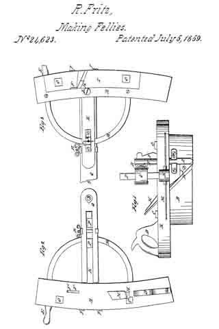
Figure 1, is an elevation of the back side of my gage plane, Fig. 2, is a. plan or top view, Fig. 3, is a plan of the under side.
The nature of my invention for dressing the edges of carriage wheels or other circles and curves, consists in combining in the arm that gages the plane devices for varying the height of the fulcrum or center, with devices for varying its length, so as to enable the operator to dress his wheel straight or square across the edge to fit the tire. Also in making the arm which guides the plane to vibrate in the plane stock, so as to adjust and fasten it as may be desired. And in arranging some screws. to adjust the bits to suit circles of different sizes.
In the accompanying drawings A, is the top of the stock and B the bottom both of which are made in the form shown in the drawing, and fastened together by the bolts C, C. The top A, has the handle D, and pin E, fastened in it, for the operator to take hold of when he works the plane. F, is the spur iron or bit inade in the form shown in the drawing and fitted to a hole in the top A, where it is held by the wedge F’, its lower end being fitted to a score in the side of the bottom B. And to hold it firmly in the score the edges are beveled and it is fitted to a dovetailed score in the piece of metal G, fastened to the bottom B, with screws as shown in the drawing. The lower end of this spur bit is V-shaped to cut a score and sever the wood in advance of the plane bit or iron H, which is fitted to a score in the side of the bottom B, and passes up through the top A, and is fastened by the wedge H’; and to prevent the side of the stock from wearing between the bits F, and H, it is faced with a piece of metal I; and the screws J, J, are arranged to act against the bits F, and H, so as to adjust them to cut circles of different sizes. In order to enable the operator to work this plane in the arc of a circle or around the rim of a wheel, I connect it to a pin or pivot, set in the center of the circle or hub of the wheel by a compound arm which consists of the bar K, fitted to a mortise in the top A, and arranged to vibrate on the screw L, and semicircle M, which is also fastened to the top A, and there is a piece of metal N, fastened to the under side of the bar K, and provided with a set screw O, to act against the circle M, and hold the bar K, in the position desired.
The standards P, P, are fastened in the top of the bar K; and the bar Q, is fitted or provided with a slot, so as to traverse both horizontally and perpendicularly on the standards P, P; and when adjusted in the position desired, it may be fastened by the clamping screw R, which passes through both arms of the bar Q, and is arranged to traverse in slots in the arms of the bar Q, as it is traversed horizontally on the standards P, P. The end of the bar Q, is perforated at S, and bushed with a piece of metal fitted to the pivot set in the center of the circle or hub of the wheel to be dressed. The wood is cut away in front of the bit H and enlarged toward the outside of the bottom, B to let the chips escape which are cnt by the bit, H.
The plane being constructed and completed as above described and the rim of the wheel to be dressed being properly fastened to the spokes and placed in a horizontal position, and a pivot set in the hub for the end of the bar Q, to work on; and the bar Q, adjusted on the standards P, P, so as bring the plane a proper distance from the center, with its top level or the inner edge little the lowest. The plane is now worked and the edge of the wheel dressed a quarter of an inch deep all around, and then the bar Q, inust be raised a quarter of an inch on the standards P, P, when the rim may be dressed a quarter of an inch deeper; and so on until it is pressed entirely across the edge as desired.
The rims of wheels may be dressed far better and quicker and with far less labor with my plane than can be with an ordinary drawing knife. And besides it will be far less labor to fit and set the tire upon them.
I believe I have described and represented my invention, so as to enable any person skilled in the art to make and use it. I will now state what I desire to secure by Letters Patent.
1. I claim combining in the arm that gages the plane devices for varying the height of the radial arm, with the devices for varying its length so as to enable the operator to dress a wheel straight or square across the edge substantially as described.
2. I claim making the arm or bar K, which guides the plane in the arc of a circle, to vibrate in the stock, so as to adjust and fasten it in the position desired.
REUBEN FRETZ.
Witnesses:
W. L. NICHOLLS,
SIDNEY CULVER.