
| PLEASE NOTE: The images presented on this page are of low resolution and, as a result, will not print out very well. If you wish to have higher resolution files then you may purchase them for only $2.95 per patent by using the "Buy Now" button below. All purchases are via PayPal. These files have all been cleaned up and digitally enhanced and are therefore suitable for printing, publication or framing. Each zip package contains all the images below (some packages may contain more), and purchased files can be downloaded immediately. |
UNITED STATES PATENT OFFICE.
_________________
AMOS FALES, OF DENVER, COLORADO.
VARIABLE BENCH-PLANE.
_________________
SPECIFICATION forming part of Letters Patent No. 254,542, dated March 7, 1882.
Application filed December 12, 1881. (No model.)
_________________
To all whom it may concern:
Be it known that I, AMOS FALES, of Denver, in the county of Arapahoe and State of Colorado, have invented an Improved Kit-Plane, or combination instrument for planing, tonguing and grooving, rabbeting, plowing, and forming beads and moldings of various forms and styles; and I do hereby declare that the following is a full and exact description thereof, reference being had to the accompanying drawings, making part of this specification —
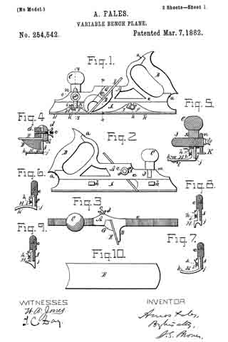
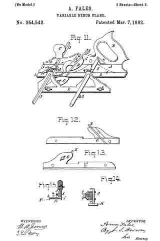
Figure 1 being a view of the near or working side of the kit-plane; Fig. 2, a view of the opposite side of the same; Fig. 3, a top view thereof; Fig. 4, a cross-section thereof in a plane indicated by the line x x, Fig. 1; Fig. 5, a cross-section in a plane indicated by the line y y, Fig. 1; Figs. 6, 7, 8, and 9, cross-sections of the stock, showing in place different forms of face-plates or molds attached to the stock; Fig. 10, a view of one of the bits or cutters used with the molds, representing two forms; Fig. 11, a view in perspective, showing an auxiliary stock or attachment, connected with the main stock by gage-bars, for various purposes; Figs. 12 and 13, respectively, opposite side views of the attachment or auxiliary stock; Figs. 14: and 15, partial sections, showing parts in detail.
Like letters designate corresponding parts in all of the figures.
My invention consists in a kit plane of simple but peculiar construction, by which are combined a stock adapted to receive any required kind of bit or cutter for producing various shapes of moldings and other outlines in wood-work, and attachable and detachable forms or molds of various shapes, to correspond with those of the cutters, for performing a great variety of work which ordinarily require many different planes or instruments.
The plane-stock A is of very simple and light construction. It may be made of metal — say of cast-iron — finished suitably, and accurate in shape, and it may have a wooden handle, B, attached to the stock by screws a a. This of course is at the rear end of the stock, and it has or may preferably have a wooden knob, C, near the front end, on top, for holding and guiding the instrument with the left hand.
On the working side of the stock, near the middle thereof, an oblique projecting ledge or bracket, D, is cast on or attached to the stock, on which ledge the various cutters used with the instrument rest when employed. Each cutter E is supported by this ledge, guided only at one edge, next to the stock, the opposite edge being free, so that various widths of cutters may be used with the stock.
Instead of a wedge working downward to fasten each cutter in the stock, I employ a wedge, G, working horizontally and entering a deep wedge-shaped notch or recess, b, in the stock, which is enlarged on the opposite side, as shown in Fig. 3, to compensate for the weakening produced by the said notch, and thereby to give uniform strength throughout the length of the stock. A horizontal screw-bolt, c, passes through the wedge G, or is otherwise made fast to it, and thence extends through and projects a little beyond the stock, on the opposite side thereof. On this screw-threaded end of the bolt a hand-nut, d, screws against the side of the stock, and thereby draws the wedge into its notch or socket, and tightens and holds the cutter fast on its ledge. Thus not only is each cutter always securely held and easily adjusted, but great facility is afforded for changing cutters.
The upper part, e, of the stock is made thick enough to give necessary strength and to suitably attach other parts directly connected therewith. The lower part, f is a thin blade or flange to which to attach the planing-molds, now to be described.
In connection with the various forms of cutters to be used in the stock, two face-plates or molds, H I, are used, one situated forward of and the other back of the cutter, substantially as shown in Fig. 1. Each pair of molds for each different form of cutter is of like form in cross-section to fit the form produced by the cutter between them and guide the plane and hold it in the proper course. Each one has a vertical flange, g, fitting against one side of the flange f of the plane-stock, and by this flange it is united to the stock with a screw, h, passing through both flanges, and a hand-nut, i, turning thereon, one screw and nut serving for each mold. For convenience in attaching and detaching the molds, the opening in the flange g to receive the screw is a notch, as shown in Fig. 1, so that the attachment and detachment can be effected without removing the nut simply by loosening and then retightening the same. To hold the molds thus attached in accurate position, there is a shoulder, j, from each under the lower edge of the stock-flange f as shown in the several cross-sections. The body or form it of each mold projects laterally from the flange in a general horizontal direction, but varied according to its form, as seen also in the several cross-sections showing different forms of molds.
Several of the more common forms of molds which may be used with this kit- plane are shown in the drawings. Thus Fig. 4 has the dado form or mold; Fig. 5, a fillister form, with adjustable gage l thereon; Fig. 6, a hollow form, for producing a convex molding; Fig. 7, a round or convex form, for producing a concave molding; Fig. 8, a bead-mold, and Fig. 9 a “snipe’s-bill” mold. All these and other molds to be used have corresponding forms of cutters at the cutting-edge thereof. Thus Fig. 10 shows a cutter having a form or cutting-edge at each end, that at one end corresponding and used with the hollow mold shown in Fig. 6, while that at the other end has a form corresponding and used with the convex mold shown in Fig. 7.
Ordinarily thus two forms of cutter may be united in one, if economy of expense and room occupied by the whole instrument is desired. These molds or face-plates may be made thin and light, since very little strain comes upon them, and they are very well and securely held on the stock. They are so simple in construction and easy of application that when any one wants any particular style of molding, bead, or other work for which he has no mold or cutter he can easily shape molds — say out of wood — a little thicker than the metallic forms, as shown, and make a cutter to correspond. In this manner, at little expense, one can supply himself with almost anything of the kind which he may desire.
Some of the cutters and molds used with this instrument require a gage-stop to limit the depth to which they shall go. Thus for the dado and fillister shown in Figs. 4 and 5 such a stop needs to be used, and I have shown in Fig. 5, as well as in Fig. 1, my construction and arrangement for this purpose. I employ a transverse bar, J, which extends through a mortise or notch, m, in the stock, and this, for convenience, is held in position by the knob C, which, screwing down on the stock, serves as a nut to hold the bar, which can thereby be adjusted longitudinally to any desired position. This bar carries the gage-stop K, the stem n of which passes up through a hole in the bar, and is held at any height to which it may be adjusted by a set-screw, o.
For some special purposes, where two cutters are required running parallel with each other, I employ a light auxiliary stock, L, as shown in Figs. 11, 12, and 13, the former figure showing the stock and the means of connecting it with the main stock, and the latter two figures showing opposite side views of the cutter-holder separate. This stock is of similar construction to the main stock, but it is not so heavy, and does not require a handle nor a holding-knob. It has a similar construction for holding and securing its cutters and similar molds, corresponding in form with the respective cutters; but the cutters and molds are placed on the other side of the stock, as compared with the main stock, so that the two stocks and their adjuncts are right and left to one another, the cutters and molds of both being inward and facing one another, as shown.
The two stocks are connected together by two bars, J M, the former fitting the mortise m in the main stock and taking the place of the gage-bar J, above described, being held in the main stock by the knob C; but it may be required to be longer than the said gage-bar for its purposes. It extends through a corresponding mortise or aperture in the auxiliary stock, and is held fast therein by a set-screw, p. The other bar, M, parallel with the former bar, passes through holes or mortises in the two stocks, and is held therein by set-screws q, that in the main stock not being represented in the drawings. The bar M may be round. By this construction the auxiliary stock may be adjusted to any desired distance from the main stock.
On the bar J a gage-stop, K, is used, similar to that on the bar J; but it is represented in Fig. 11 as constructed to slide on the bar. Its construction is shown in Fig. 14. It is secured in any position by a set-screw, o.
With a proper cutter in the holder O, together with a suitable cutter in the main stock, the two sides of a tongue for tonguing and grooving are formed. By adjusting the auxiliary stock farther from or nearer to the main stock a thicker or thinner tongue is made.
By making the cutter-holder O detachable from the auxiliary stock and attaching a dado or fillister form, P, (shown separate in Fig. 15,) to the back part of the auxiliary stock, a back fillister is produced to go with the main instrument. The cutter-holder O and fillister form P are attached to the auxiliary stock by bolts and thumb-screws s s, Fig. 11.
The above are instances which indicate also other and varied uses of which the entire instrument is capable.
This whole instrument, with all the parts herein described, by taking apart, can be packed in a box less than a foot in length, six inches in breadth, and four inches in depth, interior dimensions, and thus a complete set of such instruments becomes very portable and compact and of comparatively small cost. Instruments of the ordinary construction having all the various capabilities and uses herein specified, if made separately, would occupy many times as much space and be many times more expensive.
What I claim as my invention, and desire to secure by Letters Patent, is —
1. A kit-plane constructed with a stock, A, as described, changeable cutter E, and separate changeable front and back form-plates, H I, the said form-plates being independently attached to the stock, substantially as and for the purpose herein specified.
2. The stock A, constructed with a ledge or bracket, D, projecting from one side thereof, and of sufficient width to support all the different widths of cutters used, with the laterally-acting wedge G to clamp the cutters on the ledge, and with the vertical flange f, to one side of which the front and back form-plates are attached, substantially as and for the purpose herein specified.
3. The separate form-plates or molds H I, each constructed with the horizontally-extended body or form k, the vertical flange g, for attaching to the stock-flange f and the ledge or shoulder j, for holding them accurately in line under the flange f, substantially as and for the purpose herein specified.
4. The combination, with the stock A, of the cross-bar J and gage-stop K, the former being horizontally adjustable in the stock and the latter mounted and vertically adjustable in the cross-bar, substantially as and for the purpose herein specified.
5. The auxiliary stock L and its removable cutter-holder O and mold-forms P, in combination with the main instrument, substantially as and for the purpose herein specified.
The foregoing specification signed by me this 22d day of August, 1881.
AMOS FALES.
Witnesses:
A. C. LEWIS,
J. P. LESHEN.