
| PLEASE NOTE: The images presented on this page are of low resolution and, as a result, will not print out very well. If you wish to have higher resolution files then you may purchase them for only $2.95 per patent by using the "Buy Now" button below. All purchases are via PayPal. These files have all been cleaned up and digitally enhanced and are therefore suitable for printing, publication or framing. Each zip package contains all the images below (some packages may contain more), and purchased files can be downloaded immediately. |
UNITED STATES PATENT OFFICE.
_________________
SOLON R. RUST, OF PINE MEADOW, CONNECTICUT.
BENCH-PLANE.
_________________
SPECIFICATION forming part of Letters Patent No. 257,981, dated May 16, 1882.
Application filed September 8, 1880. (No model.)
_________________
To all whom it may concern:
Be it known that I, SOLON R. RUST, of Pine Meadow, in the county of Litchfield and State of Connecticut, have invented a certain new and useful Improvement in Bench-Planes, whereof the following is a description, reference being had to the accornpanying drawings, where —
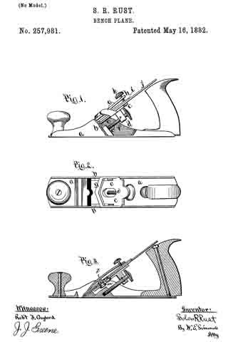
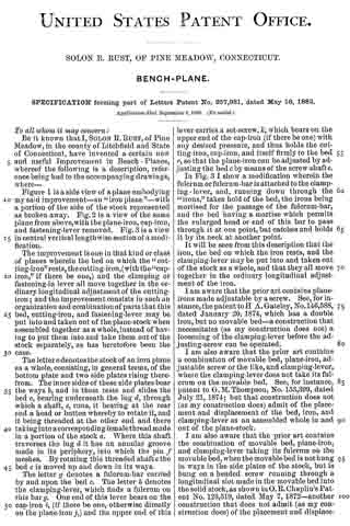
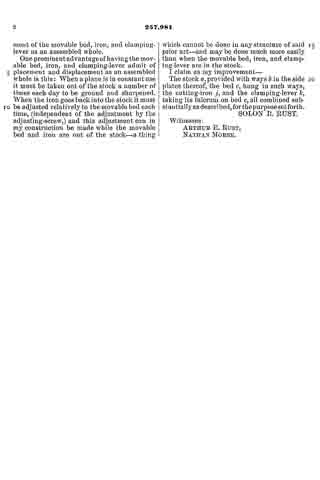
Figure 1 is a side view of a plane embodying my said improvement — an “iron plane” — with a portion of the side of the stock represented as broken away. Fig. 2 is a. view of the same plane from above, with the plane-iron, cap-iron, and fastening-lever removed. Fig. 3 is a view in central vertical lengthwise section of a modification.
The improvement is one in that kind or class of planes wherein the bed on which the “cutting-iron” rests, the cutting-iron, (with the “cap-iron,” if there be one,) and the clamping or fastening-in lever all move together in the ordinary longitudinal adjustment of the cutting-iron; and the improvement consists in such an organization and combination of parts that this bed, cutting-iron, and fastening-lever may be put into and taken out of the plane-stock when assembled together as a whole,instead of having to put them into and take them out of the stock separately, as has heretofore been the case.
The letter a denotes the stock of an iron plane as a whole, consisting, in general terms, of the bottom plate and two side plates rising therefrom. The inner sides of these side plates bear the ways b, and in them rests and slides the bed c, bearing underneath the lug d, through which a shaft, e, runs, it bearing at the rear end a head or button whereby to rotate it, and it being threaded at the other end and there taking into a corresponding female thread made in a portion of the stock a. Where this shaft traverses the lug d it has an annular groove made in its periphery, into which the pin f meshes. By rotating this threaded shaft e the bed c is moved up and down in its ways.
The letter g denotes a fulcrum-bar carried by and upon the bed c. The letter h denotes the clamping-lever, which finds a fulcrum on this bar g. One end of this lever bears on the cap-iron i, (if there be one, otherwise directly on the plane-iron j,) and the upper end of this lever carries a set-screw, k, which bears on the upper end of the cap-iron (if there be one) with any desired pressure, and thus holds the cutting-iron, cap-iron, and itself firmly to the bed c, so that the plane-iron can be adjusted by adjusting the bed c by means of the screw-shaft e.
In Fig. 3 I show a modification wherein the fulcrum or fulcrum-bar is attached to the clamping-lever, and, running down through the “irons,” takes hold of the bed, the irons being rnortised for the passage of the fulcrum-bar, and the bed having a mortise which permits the enlarged head or end of this bar to pass through it at one point, but catches and holds it by its neck at another point.
It will be seen from this description that the iron, the bed on which the iron rests, and the clamping-lever may be put into and taken out of the stock as a whole, and that they all move together in the ordinary longitudinal adjustment of the iron.
I am aware that the prior art contains plane-irons made adjustable by a screw. See, for instance, the patent to H A. Gateley, No.146,588, dated January 20, 1874, which has a double iron, but no movable bed — a construction that necessitates (as my construction does not) a loosening of the clamping-lever before the adjusting-screw can be operated.
I am also aware that the prior art contains a combination of movable bed, plane-iron, adjustable screw or the like, and clamping-lever, where the clamping-lever does not take its fulcrum on the movable bed. See, for instance, patent to G. M. Thompson, No. 153,399, dated July 21, 1874; but that construction does not (as my construction does) admit of the placement and displacement of the bed, iron, and clamping-lever as an assembled whole in and out of the plane-stock.
I am also aware that the prior art contains the combination of movable bed, plane-iron, and clamping-lever taking its fulcrum on the movable bed, when the movable bed is not hung in ways in the side plates of the stock, but is hung on a headed screw running through a longitudinal slot made in the movable bed into the solid stock, as shown in O.R. Chaplin’s Patent No. 126,519, dated May 7, 1872 — another construction that does not admit (as my construction does) of the placement and displacement of the movable bed, iron, and clamping-lever as an assembled whole.
One prominent advantage cf having the movable bed, iron, and clamping-lever admit of placement and displacement as an assembled whole is this: When a plane is in constant use it must be taken out of the stock a number of times each day to be ground and sharpened. When the iron goes back into the stock it must be adjusted relatively to the movable bed each time, (independent of the adjustment by the adjusting-screw,) and this adjustment can in my construction be made while the movable bed and iron are out of the stock — a thing which cannot be done in any structure of said prior art-and may be done much more easily than when the movable bed, iron, and clamping-lever are in the stock.
I claim as my improvement —
The stock a, provided with ways b in the side plates thereof, the bed c, hung in such ways, the cutting-iron j, and the clamping-lever k, taking its fulcrum on bed c, all combined substantially as described, for the purpose set forth.
SOLON R. RUST.
Witnesses:
ARTHUR E. RUST,
NATHAN MORSE.