
| PLEASE NOTE: The images presented on this page are of low resolution and, as a result, will not print out very well. If you wish to have higher resolution files then you may purchase them for only $2.95 per patent by using the "Buy Now" button below. All purchases are via PayPal. These files have all been cleaned up and digitally enhanced and are therefore suitable for printing, publication or framing. Each zip package contains all the images below (some packages may contain more), and purchased files can be downloaded immediately. |
UNITED STATES PATENT OFFICE.
_________________
JACOB SIEGLEY, OF NEW YORK, N. Y.
BENCH-PLANE.
_________________
SPECIFICATION forming part of Letters Patent No. 269,967, dated January 2, 1883.
Application filed May 22, 1882. (No model.)
_________________
To all whom it may concern:
Be it known that I, JACOB SIEGLEY, of the city, county, and State of New York, have invented certain new and useful Improvements in Planes, of which the following is a specification.
This invention has reference to improvements in that class of planes known as shoulder-planes, which are also used as block and rabbet planes; and it consists of means whereby the cutting-tool is rigidly clamped to the stock of the plane, and adapted to be readily adjusted after clamping, as will be more fully described hereinafter.
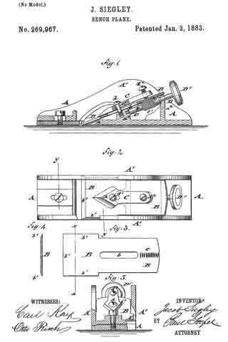
In the accompanying drawings, Figure 1 represents a vertical longitudinal section of my improved plane. Fig. 2 is a plan view of the same. Figs. 3 and 4 are a detail bottom view and a vertical transverse section on line x x, Fig. 3, of the cutting-tool employed; and Fig. 5 is a vertical transverse section of the plane on line y y, Fig. 2.
Similar letters of reference indicate corresponding parts.
In the drawings, A represents the stock of my improved shoulder-plane, which stock is made of cast metal, and provided with a flat bottom having vertical side shoulders. A’. The side shoulders, as well as the bottom, are arranged with recesses tor the inclined cutting-tool B, the narrower upper part of which is provided with a slot, b, while the lower part has three cutting-edges, b’, one at the lower end and one at each side, as customary in shoulder-planes. The slotted upper part of the cutting-tool B is clamped to interior cheeks, a1 a2, of the bottom part of the stock A by means of a tongue, C, and a clamping-screw, d, that passes through a slot, d’, of the tongue C and the slot b of the cutting-tool B, as shown clearly in Fig. 1. At the upper end of the tongue C is arranged a second clamping-screw, d2, whereby the pressure of the tongue C upon the cutting-tool B may be increased or decreased in the usual manner. The under side of the upper | part of the cutting-tool B is provided above the slot b with transverse grooves or serrations e, which are engaged by a worm-screw, e’, of a spindle, D, that is supported in inclined position parallel to the cutting-tool B, in suitable bearings of the cheeks a1 a2, the spindle being extended in upward direction, and provided with a milled or other head, D’, for taking conveniently hold of the spindle D. By turning the spindle in one or the other direction the cutting-tool B is adjusted higher or lower in the stock, as required for the stock.
By means of the adjusting mechanism described the cutting-tool in the plane can be accurately adjusted without loss of time, so that the use of the plane as a shoulder-plane or block or rabbet plane is considerably facilitated.
Having thus described my invention, I claim as new and desire to secure by Letters Patent —
1. In a shoulder-plane, the combination of a stock, A, having side shoulders, A’, and raised bottom cheeks, a1 a2, with a cutting-tool, B, a clamping-tongue, C, and means whereby the cutting-tool is adjusted in the stock, substantially as set forth.
2. The combination of a stock, A, having side shoulders, A’, and interior cheeks, a1 a2, a cutting-tool, B, having a slot, b, and transverse grooves e e at the under side, a clamping-tongue, C, and a spindle, D, supported in bearings of the cheeks a1 a2, and being provided with a worm-screw, e’, that engages the grooves of the cutting-tool B, so as to adjust the same by the turning of the spindie, substantially as and for the purpose set forth.
In testimony that l clairn the foregoing as my invention I have signed my name in presence of two subscribing witnesses.
JACOB SIEGLEY.
Witnesses:
PAUL GOEPEL,
SIDNEY MANN.