| PLEASE NOTE: The images presented on this page are of low resolution and, as a result, will not print out very well. If you wish to have higher resolution files then you may purchase them for only $2.95 per patent by using the "Buy Now" button below. All purchases are via PayPal. These files have all been cleaned up and digitally enhanced and are therefore suitable for printing, publication or framing. Each zip package contains all the images below (some packages may contain more), and purchased files can be downloaded immediately. |
UNITED STATES PATENT OFFICE.
_________________
JAMES ENGLAND, OF NEW YORK, N. Y.
CAVITY-PLANE.
_________________
SPECIFICATION forming part of Letters Patent No. 270,769, dated January 16, 1883.
Application filed April 29, 1882. (No model.)
_________________
To all whom it may concern:
Be it known that I, JAMES ENGLAND, of the city, county, and State of New York, have invented a new and useful Improvement in Hand Planing and Grooving Tools, of which the following is a full, clear, and exact description.
This invention, which is applicable to various kinds of planing and grooving tools suitable for carpenters, coopers, and other like uses, consists in a double or opposite handle-ended tool provided with an intermediate slotted metal frame and one or more cutter-holders with attached face plate or plates, and rear end projections adjustable within or through said frame and capable of being secured therein at any desired distance from the main or handle portion of the tool, whereby an implement readily convertible into different uses is obtained, and the cutting portion of the tool may be made to work at different distances from the main body of it.
Reference is to be had to the accompanying drawings, forming a part of this specification, in which similar letters of reference indicate corresponding parts in all the figures.
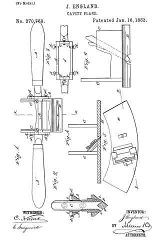
Figure 1 represents a longitudinal side elvation of a reversible or double-faced spoke-shave constructed in accordance with my invention. Fig. 2 is a transverse section of the same on the line x x; and Fig. 3, a plan of a slotted frame attached to or forming part of the handle of said tool, and serving tor the reception or adjustment of a cutter-holding frame, with its attached face plate or plates. Fig. 4 is a vertical longitudinal section on the line y y, Fig. 5, of a planing-cutter frame with attached face-plate of segmental shape and planing-cutter in its place, suitable for insertion and adjustment within the slotted frame of the handle of the tool shown in Fig. 1, in place of the double-faced spoke-shave cutter-frame arranged therein; and Fig. 5 is an inverted plan of the same. Fig. 6 is a side elevation of a grooving-cutter frame with its attached face-plate and cutter, similarly interchangeable with the spoke-shave cutter-frame shown in Fig. 1.
A in the drawings indicates an oblong metal frame, having a longitudinal slot, b, down through it, and having handles A’ A’ attached to its outer ends and guides or ways c c on the interior of its ends. Said metal frame is likewise provided with holding-screws d d on its sides and ends for securing the cutter-holding frame, with its attached face-plate and cutter or cutters, within the slotted frame A.
The tool, taken as a whole, is designed to be used as a spoke-shave, and is so used as far as the grasp and manipulation of it by the handles A’ A’ are concerned ; but the slotted metal frame A, with its screws d d, not only provides for readily converting it into various kinds of planing, grooving, or scraping tools, but also for the adjustment of the face-plate of the tool to different distances from the longitudinal center of the handle-holding portion of it. This latter provision is very advantageous, inasmuch as it admits of the face-plate, and in fact of the whole cutter-holding portion of the tool, being projected more or less beyond the main or handle portion of the tool, to work in recesses or places where it is not convenient or practicable to work the entire implement, and where the tool is a grooving one it may, by the provision which is thus secured for it, be used to cut a deeper groove beyond the general surface of the work than otherwise would be practicable.
To these ends or purposes, which are distinct from the mere adjustment of the cutter or cutters relatively to their face plate or plates, the cutter-holding portion of the tool is distinct from the handle portion of it, and is made adjustable up or down within or through the slotted metal frame A by constructing the face plate or plates B of the implement with end projections, C C, perpendicular to the face-plates, and at a suitable distance apart to be capable of sliding within or through the ends or ways c c of the slotted frame A, and of being secured therein by the screws d d at any desired projection from the handle portion of the instrument to which they may have been adjusted, such face plate or plates B, with their attached projections C C, constituting a cutter-holding frame. It is immaterial whether the implement be a spoke-shave, as shown in Figs. 1 and 3, a circular planing tool, as provided for by the constructions of the cutter-holder shown in Figs. 4 and 5, a grooving-tool, as provided for by the construction represented in Fig. 6, or any other kind of planing, grooving, or scraping tool having either single or double facing-plates. The facilities of adjusting and securing the cutter-holders, regardless of the shape of the cutters e and independent of their adjustment relatively to their face plate or plates, is the same, and the same main or handle portion of the tool may be used for different cutters or their holders, thus virtually making the implement a readily-convertible one for work of different styles or character.
Having thus described my invention, I claim as new and desire to secure by Letters Patent —
The combination with the handles A’ A’, their connecting slotted frame A, and the screws d d, of a cutter-holding frame having one or more face-plates or surfaces, B, and rear end projections, C C, fitted so as to be adjustable within or through the slotted frame A, essentially as described, and for the purposes herein set forth.
JAMES ENGLAND.
Witnesses:
C. SEDGWICK,
B. G. UNDERWOOD.


