

| PLEASE NOTE: The images presented on this page are of low resolution and, as a result, will not print out very well. If you wish to have higher resolution files then you may purchase them for only $2.95 per patent by using the "Buy Now" button below. All purchases are via PayPal. These files have all been cleaned up and digitally enhanced and are therefore suitable for printing, publication or framing. Each zip package contains all the images below (some packages may contain more), and purchased files can be downloaded immediately. |
UNITED STATES PATENT OFFICE.
_________________
LEVI C. STRONG, OF ALBANY, NEW YORK, ASSIGNOR OF THREE-FOURTHS TO PETER KINNEAR AND CHARLES H. TURNER, BOTH OF SAME PLACE.
BENCH-PLANE.
_________________
SPECIFICATION forming part of Letters Patent No. 275,538, dated April 10, 1883.
Application filed July 15, 1882. (No model.)
_________________
To all whom it may concern:
Be it known that I, LEVI CULVER STRONG, a citizen of the United States, residing at Albany,in the county of Albany and State of New York, have invented new and useful Improvements in Bench-Planes, of which the following is a specification.
I have improved the style of metallic bench-plane in which the knife is carried by a pivoted device and adapted thereby for adjustment in the arc of a circle to govern the depth of the cut. The objects of my improvements are, to provide by a single adjustment of the knife-carriage for producing a coarse or a thin shaving and a corresponding wide or narrow throat — that is to say, by a single adjustment of the knife-carriage to change the depth of the cut from a coarse to a thin shaving, the throat will be in proportion closed for fine work; to effect a greater range of adjustment of the knife or bit than is necessary for the greatest depth of cut to adapt the plane for cross-grain work and for hard and soft wood; to provide for increasing the width of the throat for the free passage of the shavings for either fine or coarse work independent of the pitch of the knife — that is to say, when a wide throat is required, without regard to the pitch of the knife or bit, as in planing across the face of a board, then the required width of throat is obtained by a horizontal adjustment of the knife-carriage upon the stock; and to provide a certain and positive adjusting and fastening device for setting and maintaining the knife or bit in whatever position it may be adjusted in relation to its carriage, while at the same time such adjustment may be easily and quickly effected for the finest work These objects I attain by the construction and means of adjustment illustrated in the accompanying drawings, in which —
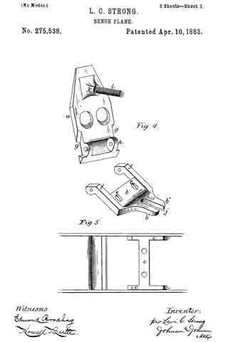
Figure 1 represents a vertical longitudinal section of a bench-plane embracing my invention; Fig. 2, a top view, the knife being removed to show the knife-carriage. Fig. 3 shows the two parts or sections of the knife-carriage and the adjusting device. Fig. 4 shows the two sections of the knife-carriage separated; and Fig. 5, a top view of so much of the stock as shows the seat upon which the knife-carriage is secured.
The stock of the plane is cast and provided with the usual throat for the knife and with the handle and front knob. The carriage for the knife or bit consists of two parts — viz., a seat-plate, a, upon which the knife is secured, and a base-plate, b, pivoted to the seat-plate, so that the latter can be adjusted in the arc of a circle upon its pivoted connection. The base-plate b is secured upon a raised rib, c, cast upon the upper side of the bottom of the stock by two screws, d d, passing through slots e e in the base-plate, whereby it may be adjusted horizontally in relation to the throat, its pivot joining with the seat-plate, as formed by arms f f the ends of which fit into recesses g g, preferably at the opposite edges of the seat-plate and against ears h h on its under side, through which and the ends of the arms the pivot-pin i passes, so as to bring the pivot-joined end of the seat-plate in close proximity to the rear edge of the throat. The rear end of the base-plate is curved or inclined upward and terminates in arms b’, so as to form a slot, j, in longitudinal central position with the stock. The seat-plate is formed with a boss or projection, k, on its under side, in the middle of its width and near its upper rear end, into which a screw-stem, l, is screwed tight, having a length sufficient to extend down through the slot j of the base-plate. Milled thumb-nuts m m are placed upon the screw-stem above and below the rear arms of the base-plate, and as the latter has a fixed relation to the stock the seat-plate can be turned upon its pivot-pin, so as to increase or diminish its angle or pitch by turning the thumb-nuts to the right or to the left, in which action one of said nuts will form a jam or lock nut against the arms of the base-plate, and thus form a positive and secure lock to the knife-carriage when set. The slotted end of the base-plate for this purpose stands high enough above the bottom of the stock to allow of easily manipulating the lower thumb-nut. This construction not only gives a very fine adjustment to the seat-plate, but affords the means by which it is secured against any accidental displacement from its adjustment. In making the adjustment the nuts are turned separately by the thumb of one hand, so that one nut follows the other up or down upon the screw-stem above and below the arms of the base-plate. The base-plate, the seat-plate, and the adjusting screw-stem and nuts constitute a device complete for attachment to the bottom of the stock, and for this purpose the seat-plate has holes through which to insert a. screw-driver to secure the base-plate to the stock.
The knife or bit n may be used either single or double, and is secured upon the seat-plate by a headed screw, r, tapped into said plate, its head passing through a slot in the knife-blade and through a locking-eye in the usual separate cap or clamp, which is provided with a fastening-screw or cam-lever, s, operating upon a spring riveted to the under side of the cap in the usual manner. In adjusting the bit or knife for a heavy or light cut by turning the thumb-nuts, the pitch or angle of the knife turning on its pivot-pin opens or closes the throat in proportion to the thickness of the cut, and one adjustment of the bit effects these two things. To give a freer passage for the shaving without moving the base-plate, set the knife for a coarse cut, and then, placing the plane on a flat surface, unclamp the cap, which allows the knife to slide up so as to bring its cutting-edge in position in the throat for a fine shaving.
If it is desired to work with the knife at at high pitch or angle and still have a narrow throat, the base-plate is set forward by removing the knife and unclamping the fastening-screws of the base-plate, and thus the plane is set for cross-grain work. The rib c of the stock is wide enough to give a good bearing for the base-plate and hold for its securing-screws, and high enough to carry the seat-plate free of the bottom of the stock.
I claim —
1. The combination of the stock of a bench-plane with a knife-carriage composed of two plates pivoted together at their front points, the upper one, a, of said plates having the rigidly-connected screw-stem l projecting from its rear or underside, and the bottom horizontal plate, f, adjustably connected to the bottom of the plane-stock, and having an upwardly-projecting slotted arm, b’, with means, substantially as described, for adjustably connecting the said screw-stem of the upper plate with the said slotted arm of the bottom plate, substantially as described.
2. The combination, in a bench-plane, of a carriage for the knife or bit, composed of the upper seat-plate, a, having the rigidly-connected screw-stem l, and a horizontal base-plate, f, adjustably secured to the bottom of the stock, and having an upward-projecting slotted arm, b’, the said plates being pivoted together at their front points, and the thumb jam-nuts m m, arranged upon said screw-stem and bearing upon the opposite sides of said slotted arrn, substantially as described, for the purpose specified.
3. The knife-carriage of a plane-stock, composed of the seat-plate a and the base-plate b, pivoted together, the former provided with a fixed screw-stem, l, and the latter having slots e e, and an elevated slotted part, b’ j, in combination with the adjusting lock-nuts m m, the base confining screws d d, and the knife or bit n, secured to said seat-plate, substantially as described, for the purpose specified.
4. In combination in a bench-plane, the stock, having the bottom rib, c, a knife-carriage of two pivot-joined parts, one, a, provided with a fixed screw-stem, l, and the other having an upward-projecting slotted part, b’ j, to receive said screw-stem, the thumb lock-nuts m m, the screws d d, and the knife or bit n, all constructed substantially as herein set forth.
5. The combination, with the stock and the knife or bit, of a carriage for the knife, composed of two pivot-joined parts, and means, substantially as described, whereby the upper of the pivot-joined parts is adapted for adjustment upon the lower part in the are of a circle, and the latter is adapted for adjustment horizontally with the upper part upon the stock, substantially as described, for the purpose specified.
6. The knife-carriage for a bench-plane, consisting of the base-plate b, having the front arms, f f the slots e e, and the rear upwardly-projecting slotted part, b’ j, the seat-plate a, having the front edge recesses, g g, and the ears h h, and the fixed screw-stem l, projecting downward from its rear end, the pivot-pin joining the arms f f and ears h h, and the adjusting thumb lock-nuts m m, arranged upon the screw-stem above and below said slotted base part j, all constituting a complete device for carrying, adjusting, and securing the knife to the stock, as set forth.
In testimony whereof I have hereunto set my hand in the presence of two subscribing witnesses.
LEVI CULVER STRONG.
Witnesses:
A. E. H. JOHNSON,
J. W. HAMILTON JOHNSON.