| PLEASE NOTE: The images presented on this page are of low resolution and, as a result, will not print out very well. If you wish to have higher resolution files then you may purchase them for only $2.95 per patent by using the "Buy Now" button below. All purchases are via PayPal. These files have all been cleaned up and digitally enhanced and are therefore suitable for printing, publication or framing. Each zip package contains all the images below (some packages may contain more), and purchased files can be downloaded immediately. |
UNITED STATES PATENT OFFICE.
_________________
H. C. HUNT, OF OTTUMWA, IOWA.
BENCH-PLANE.
_________________
Specification of Letters Patent No. 27,983, dated April 24, 1860.
_________________
To all whom it may concern:
Be it known that I, H. C. HUNT, of Ottumwa, in the county of Wapello and State of Iowa, have invented a new and useful Improvement in Bench-Planes; and I do hereby declare that the following is a full and exact description thereof, reference being had to the accompanying drawings, which form a part of this specification.
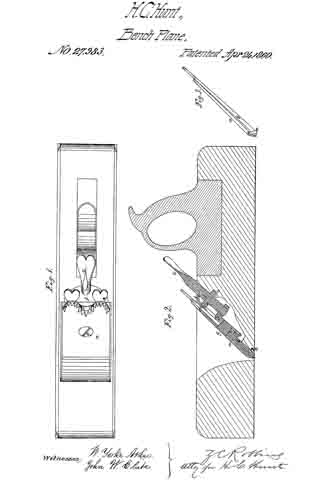
In the said drawings Figure 1, is a top view of my improved bench-plane; Fig. 2, a longitudinal section of the same, and Fig. 3, an edge view of the plane-bits detached from the stock.
The double bits a, b, in my improved bench-plane, are combined with each other, and with the plane-stock in the manner represented in Fig. 2, of the drawings, viz: the cutting bit b, has a central slit which passes from its upper end about two thirds the length thereof.
A metallic plate f, which is secured to the after side of the throat of the plane-stock, is of such a shape that it furnishes a metallic bearing surface for the cutting bit b, and also the requisite supporting and guiding bearings for the set-screw c. The screw shank of the set-screw c, is received into a screw-aperture in the angular nut d, which works in a slot in the throat-plate f. The cutting bit b, is combined with the front bit a, and also with the angular screw-nut d, by means of the screw g, which passes, first, through an aperture in the front bit a, then through the slit in the cutting bit, and then into the screw-aperture in the nut d. It will therefore be perceived that while the two bits a, and b, can be simultaneously moved outward or inward by turning the set-screw c, the cutting bit can also be readily adjusted so as to cause its cutting edge to project any desired distance beyond the closely embracing lower end of the front it, a.
It is well known that the cutting edge of a plane bit is more dulled and injured by the reverse movement of the plane over the surface of a board, than it is during its forward movement; which injurious action I have succeeded in entirely preventing by means of an attachment to the bits of my improved plane which I will now proceed to describe. A protecting metallic strap e, whose turned-up extremities are pivoted to the edges of the lower end of the front bit a, loosely embrace the lower end of the cutting bit b, so that when the plane is shoved forward, the said strap will swing freely upward into a notch which is formed in the plane-stock for its reception; but when a rearward movement is imparted to the plane, the said metallic strap will be drawn outward to a position that will cause it to elevate the front portion of the plane-stock a sufhcient distance above the face of the board that it may be operating upon, to prevent the cutting-bit from touching the surface of the board during the said reverse movement of the plane.
Having thus fully described my improved bench-plane, what I claim therein as new and desire to secure by Letters Patent, is —
Combining the metallic swinging strap e, with the bits of said plane substantially in the manner and for the purpose herein set forth.
The above specification of my improvement in bench-planes, signed and witnessed this 6th day of Feb., 1860.
H. C. HUNT.
Witnesses:
JAMES S. HARLAN,
ALBERT BALDWIN.


