
| PLEASE NOTE: The images presented on this page are of low resolution and, as a result, will not print out very well. If you wish to have higher resolution files then you may purchase them for only $2.95 per patent by using the "Buy Now" button below. All purchases are via PayPal. These files have all been cleaned up and digitally enhanced and are therefore suitable for printing, publication or framing. Each zip package contains all the images below (some packages may contain more), and purchased files can be downloaded immediately. |
UNITED STATES PATENT OFFICE.
_________________
SOLON R. RUST AND ARTHUR E. RUST, OF PINE MEADOWS, ASSIGNORS TO THE MERIDEN PATENT NOVELTY COMPANY, OF MERIDEN, CONN.
BENCH-PLANE.
_________________
SPECIFICATION forming part of Letters Patent No. 279,885, dated June 19, 1883.
Application filed February 24, 1883. (No model.)
_________________
To all whom it may concern:
Be it known that we, SOLON R. RUST and ARTHUR, E. RUST, citizens of the United States, residing at Pine Meadow, in the county of Litchfield and State of Connecticut, have invented certain new and useful Improvements in Bench-Planes; and we do hereby declare the following to be a full, clear, and exact description of the invention, such as will enable others skilled in the art to which it appertains to make and use the same.
Our invention relates to improvements in what are termed “block-planes;” and the object is to produce a plane in which the bottom or face of the plane can be easily adjusted to the iron by means of a hinge motion in back part of plane, and to produce a clamping-bar with central point bearing against a central bearing, cast solid with the frame without a core, and to form a check-nut and knob on the adjusting-screw, and also to simplify the general construction and operation.
Our invention consists in constructing a block-plane so that the plane bit or iron which projects through the mouth or opening can be adjusted, as desired, to form an open or close mouth, and to suit the nature of the work to be performed in an expeditious manner. The bottom or face of the plane is hinged to the rear part of the skeleton frame or stock, and is adjusted by means of a flat wheel on an adjusting screw or stud, and fitting with one side under lugs cast on the frame at its front end, and with the other side against two cross-bars, also cast on said frame. A check-nut and knob on said adjusting-screw secures and locks the wheel in place.
It also consists in holding the bit or plane-iron in place by a screw in the clamping-bar against said iron, while said clamping-bar bears with its upper side against a central point east solid in the frame, and which forms a fulcrum for it. The lower side of the plane-iron rests against two cross-bars, also cast solid with the frame.
It also consists in adjusting the open and close mouth without a movable front piece; and it also consists in the construction and arrangement of certain parts of a plane, as will be more fully described hereinafter, and specifically pointed out in the claims, reference being had to the accompanying drawings and the letters of reference marked thereon.
Like letters indicate like parts in the different figures of the drawings, in which —
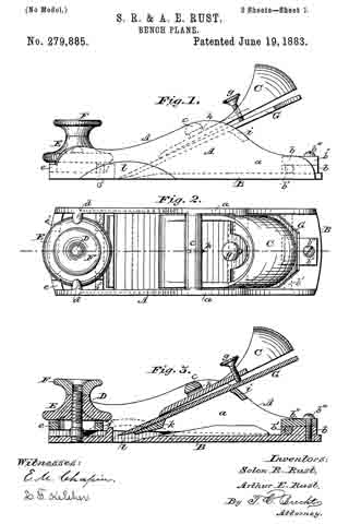
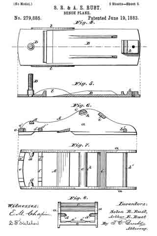
Figure 1 represents a side elevation of the plane. Fig. 2 is a top view of the same. Fig. 3 is a longitudinal section of the same. Fig. 4 is a top view of the bottom of the plane. Fig. 5 is a longitudinal section of the same. Fig. 6 is a longitudinal section of the frame. Fig. 7 is a top view of the same. Fig. 8 is an end view of the same.
In the drawings, A represents the skeleton frame or stock, consisting of the side pieces, a a, connected by a series of cross pieces or bars, one of which, b’, forming the hinge-pin for the bottom B, and another one, c, being the central bearing for the clamping-bar C. The bottom is provided with a lug, b, into which the bar b’ fits, and is held in place by a clamping-plate, b”, and screw b”’. At the forward end of the plane is arranged a screw, D, upon which a flat milled wheel, E, is screwed, fitting with its upper surface under lugs d, cast on each side or wall of the frame, and with its lower surface bearing on two bars, e and f. A milled clamping-screw or check-nut, F, secures the wheel in its locked position. By this arrangement the bottom or face of the plane can be adjusted, to a nicety to the plane iron or bit. The bars e and f are provided with raised parts e’ and f’, to form a more perfect adjustment for the wheel. The clamping-bar C secures the plane iron or bit G in position by means of a screw, g, which forces the bar G against a central bearing, h, on the bar c, cast solid with the frame and without the use of a core. The lower side of the plane iron or bit rests on two cross-bars, i k, also cast on the frame. The bottom is provided with two curved ears, l, which it closely into corresponding recesses formed in the frame, and they serve to hold the bottom in position and prevent any lateral movement. It will be readily seen that by screwing the face or bottom close down or tight, and setting the iron or bit, an open mouth is formed; and by letting the face or bottom down and then setting the iron or bit a very close mouth is obtained. A much greater pitch is also obtained by having the adjustment at the front end of the plane than if on the back under the cutting-iron, which is a great advantage, as it makes a much smoother cut. The bit can be adjusted nicely to coarse or fine work.
Having thus described our invention, what we claim, and desire to secure by Letters Patent, is —
1. In a plane, a flat wheel, E, for adjusting the size of the throat of the plane, and having its bearings on the bars e f and under lugs d, as shown, in combination with ascrew, D, secured to the hinged bottom B, substantially as specified.
2. The adjustable bottom B, hinged at the rear end of the frame A by means of a bar, b’, having bearings in a lug, b, and held by a clamping-plate, b”, and adjusted at the front end by a screw, D, and wheel E, in the manner shown and set forth.
3. The frame A, provided with a bar, c, having a central bearing, h, for forming a fulcrum for the clamping-bar C, provided with a screw, g, by which the bit G is held in place in the plane, substantially as specified.
4. The skeleton frame A, provided with bars e f and lugs d d, forming bearings for the wheel E, a bar, c, having central bearing, h, against which the clamping-bar G bears, and the pivot-bar b’, forming the hinge-bar for the adjustable bottom, and all cast in one piece, as set forth.
5. The method of and means herein described for adjusting the bottom B to form an open and close mouth — that is to say, connecting the bottom to the frame by a hinge-joint, b b’ b”, and adjusting it by a screw, D, and wheel E, substantially in the manner shown and specified.
6. In a plane, a wheel, E, for adjusting the size of the throat, having bearings on bars e f, and under lugs d, and a lock-nut, F, for securing said wheel, in combination with the screw D, secured to the hinged bottom B, as shown and described.
7. The combination of a hinged bottom, B, provided with curved ears l, fitting into corresponding recesses in the sides of the skeleton frame A, with a bit, G, held in place by a clamping-bar, C, and thumb-screw g, the stationary screw D, and wheel E, for adjusting the bottom, substantially as described, and for the purpose set forth.
8. The plane herein described, consisting of the skeleton frame A, to which the bottom B is hinged adjustably, in combination with a screw, D, clamping-wheel E, check-nut F, bit G, clamping-bar C, with screw g, and central bearing-point, all constructed and arranged substantially as specified.
In testimony whereof we hereby affix our signatures in presence of two witnesses.
SOLON R. RUST.
ARTHUR E. RUST.
Witnesses:
E. M. CHAPIN,
E. E. KELLOGG.