
| PLEASE NOTE: The images presented on this page are of low resolution and, as a result, will not print out very well. If you wish to have higher resolution files then you may purchase them for only $2.95 per patent by using the "Buy Now" button below. All purchases are via PayPal. These files have all been cleaned up and digitally enhanced and are therefore suitable for printing, publication or framing. Each zip package contains all the images below (some packages may contain more), and purchased files can be downloaded immediately. |

UNITED STATES PATENT OFFICE.
_________________
ARTHUR T. GOLDSBOROUGH, OF WASHINGTON, DISTRICT OF COLUMBIA.
BENCH-PLANE.
_________________
SPECIFICATION forming part of Letters Patent No. 284,732, dated September 11, 1883.
Application filed March 29, 1883. (No model.)
_________________
To all whom it may concern:
Be it known that I, ARTHUR T. GOLDSBOROUGH, a citizen of the United States, residing at Washington, in the District of Columbia, have invented certain new and useful Improvements in Metallic Bench-Planes; and I do declare the following to be a full, clear, and exact description of the invention, such as will enable others skilled in the art to which it appertains to make and use the same, reference being had to the accompanying drawings, and to the letters and figures of reference marked thereon, which form a part of this specification.
My invention relates to improvements in carpenters’ bench-planes; and it consists in providing a metallic plane of substantially the ordinary form, with two blades or bits especially adapted for use on coarse and fine work, respectively, but which may be used interchangeably; and, further, in so arranging said bits that all locking devices are dispensed with, the blades being arranged on convergent intersecting lines, so that the idle one, by being forced against its companion through the me-
dium of its adjusting-screw, acts to securely hold it in the desired position.
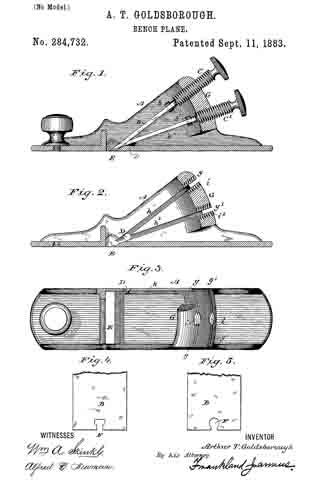
In the accompanying drawings, Figure 1 is a longitudinal sectional elevation, showing the general plan of construction and arrangement. Fig. 2 is a longitudinal sectional elevation of the stock or frame, the bits and adjusting-screws being removed. Fig. 3 is a plan view of the stock or holder, having a portion of the bridge and frame broken away to show the course of the interior grooves. Figs. 4 and 5 are detail views of the bits, showing the preferred mode of connecting the adjusting-screws thereto.
Similar letters denote like parts.
A represents the stock or frame, which is in many respects similar to those now in use.
G is a cross-piece or bridge, preferably formed integral with the remainder of the frame, and it is slitted and apertured as shown. The slits g g’ form entrances to grooves h h’, formed in the body of the stock, which grooves lead from the said slits and converge at the throat E, intersecting a short distance above that point. The circular apertures i i’ are internally screw-threaded, and lie in the same plane as the slits and grooves.
The bits B B’ are of ordinary shape and bevel, and are formed with spherical or T-shaped slots F at their upper ends.
The screws C C’ are provided with milled heads, and with spherical or T-shaped extensions b b’ at their inner ends, which register with the slots F. The screws C C’ are to be used in the apertures i i’ interchangeably, and are consequently of the same diameters.
The bits are placed in their respective slots, and the. heads b b’ in the slots F, when by turning the screws the bits are forced down until their converging ends meet, or until the heel of the bevel of one bit rests against the under or upper side of the bit, below or above it, as the case may be, when they will be securely locked each by the other. The lower bit having its beveled side up, and the upper one its beveled side down, it will be seen that the angle of contact between the bits is such that the cutting-edges never interfere, the bits touching only with the heel of one against the flat surface of the other. It is intended to use the upper bit for coarse work and the lower or reversed one for finishing.
The screw C is here shown longer than the one C’. Being interchangeable, it is preferred to exchange them when reversing the position and function of the bits in order to have them project about an equal distance from the bridge.
It will be found convenient to provide a spare screw of extra length for use when either of the bits becomes very much shortened. The same screw may be also used to lock the upper bit if it should be found desirable to use one bit only, the end of the screw acting as a wedge, and resting against the under side of the bit and the upper side of the interior of the stock.
By means of an aperture, D, any convenient instrument can be inserted to force the bits from one side to the other, they being allowed the ordinary amount of lateral movement, and it also allows the position and relation of the locking to that of the cutting blade to be observed. For planes of larger sizes a rear handle of any of the well-known forms will be added.
Having described my invention, I claim —
1. A bench-plane having a pair of blades or bits permanently arranged therein on convergent lines, said lines intersecting and crossing at a point above a common throat, substantially as set forth.
2. A bench-plane having a pair of cutting blades or bits arranged on convergent intersecting lines, a pair of interchangeable adjusting-screws detachably secured thereto, and suitable stock or frame, substantially as set forth.
3. In a bench-plane, a stock or frame formed with a pair of grooves intersecting at a point above the throat and diverging therefrom, and a bridge or brace forming part thereof, and slitted to form continuatious of said grooves, and adapted to allow the insertion and adjustment of the cutting blades or bits and controlling device, substantially as described.
4. A bench-plane consisting, essentially, of the combination of a stock or frame formed with a pair of grooves intersecting above the throat and diverging therefrom, and a bridge slitted to form continuatious of said grooves, a pair of cutting blades or bits adapted to be moved in convergent intersecting lines therein, and adjusting-screws detachably secured thereto, and having bearings in said bridge, whereby the bits may be used independently or as cutters and locking devices, respectively, substantially as set forth.
5. As an article of manufacture, a bench-plane having a pair of cutting blades or bits arranged on convergent intersecting lines, said bits being adapted for use as cutting and locking devices, respectively and interchangeably, a pair of interchangeable adjusting-screws detachably secured to said bits, and a suitably grooved and apertured stock or frame, substantially as set forth.
6. A plane stock or frame having the lateral apertures D located at the intersection of the cutting and locking blades, as set forth.
7. The combination, with stock A, formed with grooves h h’ and throat E, and the slitted and apertured bridge G, of the bits B B’, and adjusting-screws C C’, substantially as shown and described.
In testimony whereof I affix my signature in presence of two witnesses.
ARTHUR T. GOLDSBOROUGH.
Witnesses:
JOHN H. DEWANDELAER,
FRANKLAND JANNUS.