
| PLEASE NOTE: The images presented on this page are of low resolution and, as a result, will not print out very well. If you wish to have higher resolution files then you may purchase them for only $2.95 per patent by using the "Buy Now" button below. All purchases are via PayPal. These files have all been cleaned up and digitally enhanced and are therefore suitable for printing, publication or framing. Each zip package contains all the images below (some packages may contain more), and purchased files can be downloaded immediately. |

UNITED STATES PATENT OFFICE.
_________________
JUSTUS A. TRAUT, OF NEW BRITAIN, CONNECTICUT, ASSIGNOR TO THE
STANLEY RULE AND LEVEL COMPANY, OF SAME PLACE.
BEADING-TOOL.
_________________
SPECIFICATION forming part of Letters Patent No. 284,777, dated September 11, 1883.
Application filed June 12, 1883. (No model.)
_________________
To all whom it may concern:
Be it known that I, JUSTUS A. TRAUT, a citizen of the United States, residing at New Britain, in the county of Hartford and State of Connecticut, have invented certain new and useful Improvements in Beading-Tools, of which the following is a specification.
My invention relates to improvements in beading-tools; and the objects of my improvements are the convenient adjustment for different sizes of cutters, and to make a cheap, efficient, and convenient tool especially adapted for forming beads. I attain these objects by the simple construction illustrated in the accompanying drawings, in which —
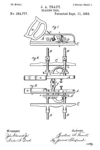
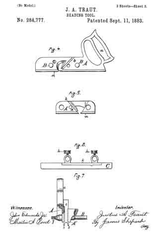
Figure 1 is a side elevation of my improved beading-tool. Fig. 2 is a plan view thereof. Fig. 3 is a reversed plan view. Fig. 4 is a side elevation of one part of the stock. Fig. 5 is a side elevation of the confronting face of the companion part of the stock. Fig. 6 is a side elevation of the gage; and Fig. 7 is a vertical section of my beading-tool on line x x of Fig. 1, the same being represented with the cutter as drawn up a little, in order to better show the lower working faces of the stock.
My beading-tool is designed for use by hand, the same as other bench-tools — such as plows, planes, &c. — and belongs to that class of tools known under the general term of “bench-planes.”
A designates the main portion of the stock, the same being provided with a suitable handle, a, either separately formed and attached thereto or made all in one and the same piece, as may be desired. This part of the stock, instead of being specially designed for a beading-tool and nothing else, may, if desired, be so formed as to constitute a part of a plow, dado, or other planing-tool. A’ designates the companion part of the plane-stock. Both of these parts have a groove, b, Figs. 4 and 5, upon their inner face, for the reception of a cutting-bit or cutter, and when the parts are put together these grooves are directly opposite to each other, and form, in substance, a single seat for the two edges of one cutter, c. The two parts of the stock are united by means of guide-rods B B, which are rigidly secured to the main part A of the stock, while the companion part, A’, is arranged to slide upon said rods. This companion part, A’, of the stock is provided with a screw or bolt, d, which is rigidly secured to said part, and which passes through an orifice in the main part A of the stock. The end of this screw is provided with a thumb-nut, g, which, with the screw d, acts as a clamping mechanism. The working-faces s s of the stock A and A’ are quite small and narrow, as shown. The cutter c, of any desirable width, is placed with its two opposite edges in the groove b in the stock, and the thumb-screw g is tightened to bind said cutter edgewise firmly in place. This arrangement not only allows for inserting cutters of different widths and of different shapes at the cutting end, but also constitutes a new means for clamping a cutter within the stock, and the ordinary means for securing the cutter are thereby dispensed with.
Upon the rods B B, which connect the two parts of the stock, the gage C is secured, and provided with set-screws h for adjusting it in any desired position. This gage is recessed upon its inner face, as shown at k, Figs. 1 and 6, so that it may receive bodily into it the lower edge of the part A’ of the stock, and thereby cover up, on one side of the tool, that portion of the cutter c which cuts a groove by the side of the bead, so that the tool may be used for forming a bead at the corner of an article when desired.
n n designate spurs for cutting the grain of the wood, which spurs are substantially the same as in other tools of this class.
D designates the bottom gage for regulating the depth of the cut, which gage is substantially the same as that used in plows and analogous tools. The grooves b in the stock are formed with the bottom substantially flush with the outside of the stock at its lower end, as shown most clearly in Fig. 7, whereby the outer faces of the stock are always substantially flush with the outer vertical faces of the cutter, no matter what width of cutter is secured between the two parts of the stock. This fea-
ture in a plane-stock composed of two parts, so as to always bring the outer vertical faces of the stock in proper position to the cutter, is found in am prior patent issued to myself March 4, 1873, but 11ot in connection with the manner of clamping the tool hereinbefore described.
I claim as my invention —
In a bench-plane, the combination of the two-part stock having cutter-grooves formed in the confronting faces of said parts, for receiving the edge of the cutter, and mechanism for binding the two parts of the stock upon the cutter to clamp it edgewise, substantially as described, and for the purpose specified.
JUSTUS A. TRAUT.
Witnesses:
HENRY S. WALTER,
WILLIAM j. WORAM.