
| PLEASE NOTE: The images presented on this page are of low resolution and, as a result, will not print out very well. If you wish to have higher resolution files then you may purchase them for only $2.95 per patent by using the "Buy Now" button below. All purchases are via PayPal. These files have all been cleaned up and digitally enhanced and are therefore suitable for printing, publication or framing. Each zip package contains all the images below (some packages may contain more), and purchased files can be downloaded immediately. |


UNITED STATES PATENT OFFICE.
_________________
JOHN M. BENNETT, OF GREEN ISLAND, NEW YORK, ASSIGNOR TO
HENRY C. BAILEY, OF COVINGTON, KENTUCKY.
RABBET-PLANE.
_________________
SPECIFICATION forming part of Letters Patent No. 284,941, dated September 11, 1883.
Application filed August 18, 1882. (No model.)
_________________
To all whom it may concern:
Be it known that I, JOHN M. BENNETT, a citizen of the United States, residing at the village of Green Island, in the county of Albany and State of New York, have invented new and useful Improvements in Rabbet-Planes, of which the following is a specification.
My invention relates to improvements in rabbet-planes; and the objects of my improvements are to provide a strong and durable stock and base or bed-piece of suitable metal, having a cutter adjusted by means of a cap and screw, and also a guide or fence, so that it can be used with either hand and as a fillister. I attain these objects by the mechanism illustrated in the accompanying drawings, in which —
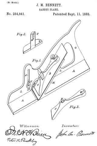
Figure 1 is a view in perspective of the plane complete. Fig. 2 is a view in perspective of the guide or fence. Fig. 3 is a view in perspective of the cap.
Similar letters refer to similar parts throughout the several views.
The stock L extends along the right side of the base or bed-piece A and at a right angle thereto, and has a suitable handle, O, at the rear end thereof. At a suitable point in the base or bed-piece A a throat is cut through and entirely across said base or bed-piece, into which throat the cutting-edge of the cutter B is placed and worked. Running from the rear side of the throat upward, upon a proper angle toward the rear of the stock, and cast thereon or fastened thereto, is the cutter-rest M, which is straight and flat, and upon which the cutter rests.
The cap C is a littler shorter than the cutter-rest M, and at the end placed near the throat is of the same width as thecutter, and is flat upon the under side and beveled to an edge upon the upper side. The under side of the cap C is flat and slightly concave to a point from the lower end for about two-thirds its length, from which point it is straight and inclined slightly upward. The upper side of said cap C is irregular in form, being the highest and narrowest at the point where the slot K is cut, and slightly convex from thence to the lower end and concave to the upper end. It is obvious, however, that any other form from the beveled end upward that will give a bearing at the slot K and lower end, and by means of the screw J at the upper end properly hold the cutter B in its position, may be used. Passing through the upper end of the cap C is a screw, J — a thumb-screw being the most convenient — the lower end of which is in contact with the upper side of the cutter B, and by means of which the pressure of the cap upon the cutter is regulated and the cutter held firmly in position or removed. At the highest point of the cap C, and upon the upper side thereof, is out crosswise a slot, K, to admit therein the lug or brace D, by means of which the cap is prevented from moving lengthwise. The lug or brace D is cast upon or fastened to the inside of the stock L, at a point about midway the throat and the upper end of the cutter-rest M, and projects over and a little beyond the center of said cutter-rest. Its size and shape are such as to be adapted to the use to which it is to be put. Through the stock L, at the front side of the throat, is cut a perpendicular slot, G, of any required width and length.
The guide E is a flat smooth piece, of suitable material and size, having firmly attached an upright, with a shoulder, F, made to fit and work in the slot G, and thus keep the base-piece of the guide always parallel to the base or bed-piece A. This guide is placed upon the outside of the stock K, and firmly fastened thereto by means of a screw, N, which passes through the slot G and into a suitable opening, having a corresponding thread cut therein, in the said upright. This guide may be raised or lowered at pleasure, and thus regulate the depth of the cut of the plane. A suitable opening is made through the stock L, extending a short distance upward from the throat in a line with the cutter, to allow the cuttings of the cutter to pass away from the throat, and this opening, as well as the throat, should be of such size and shape as are best adapted to a free and easy discharge of the cuttings of the cutter.
The cutter may be of much the same kind as those in ordinary use in planes. The lower or cutting end is of the same width as the face of the base or bed-piece A, and continues that width the length of the opening aforesaid in the stock L, and is from thence of about the same width as the cutter-rest M.
The handle O is of proper size and shape to fit the hand, and may be east as a part of and with the stock. Thus the base or bed-piece A, the stock L, handle O, lug or brace D, and cutter-rest M may all be cast of iron or other suitable metal, at one time and in one piece, forming a tool that will not warp or wear and work to a sharp corner. The size, of course, may be such as is required.
I am aware that prior to my invention rabbet-planes have been made. I therefore do not claim such plane, broadly; but
What I do claim as my invention, and desire to secure by Letters Patent, is —
In a plane, the stock L, having the slot G made through it, in combination with the guide E, provided with the flange F, and the set-screw H, for holding the guide in position, substantially as shown.
JOHN M. BENNETT.
Witnesses:
JNO. H. O’BRIAN,
PETER H. BUCKLEY.