
| PLEASE NOTE: The images presented on this page are of low resolution and, as a result, will not print out very well. If you wish to have higher resolution files then you may purchase them for only $2.95 per patent by using the "Buy Now" button below. All purchases are via PayPal. These files have all been cleaned up and digitally enhanced and are therefore suitable for printing, publication or framing. Each zip package contains all the images below (some packages may contain more), and purchased files can be downloaded immediately. |
UNITED STATES PATENT OFFICE.
_________________
WILLIAM B. FENN, OF MERIDEN, CONNECTICUT,
ASSIGNOR TO FOSTER MERRIAM & CO., OF SAME PLACE.
JOINER’S PLANE.
_________________
SPECIFICATION forming part of Letters Patent No. 287,371, dated October 23, 1883.
Application filed June 30, 1883. (No model.)
_________________
To all whom it may concern:
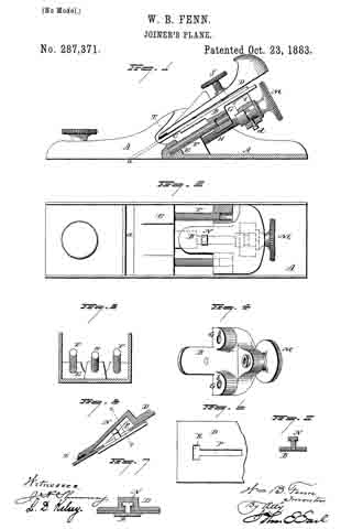
Be it known that I, WILLIAM B. FENN, of Meriden, in the county of New Haven and State of Connecticut, have invented a new Improvement in Joiners’ Planes; and I do hereby declare the following, when taken in connection with accompanying drawings and the letters of reference marked thereon, to be a full, clear, and exact description of the same, and which said drawings constitute part of this specification , and represent, in —
Figure 1, a sectional side view; Fig. 2, a top view, with the plane-iron and clamp removed; Fig. 3, a rear view, the bed removed, showing the inclined guiding-sides and screw. Fig. 4, a perspective view of the bed removed, looking toward the under side; Fig. 5, a longitudinal section of the clamp through the T-shaped slot; Fig. 6, an under side view of the clamp; Fig. 7, a transverse section of the clamp on line x x of Fig. 5; Fig. 8, a transverse section of the bed, showing the T-shaped stud.
This invention relates to an improvement in that class of joiners’ or bench planes in which mechanism is employed to adjust the cutter with relation to the thickness of the shaving to be cut. In the more general construction of this class of planes the bed is fitted to work upon ways in the stock. These ways, as well as the bed, require to be shaped or fitted in the planing-machine, and this fitting of the bed and ways is an expensive part of the manufacture of the plane.
The principal object of my invention is to avoid this expensive part of the work; and the invention consists in the construction of plane as hereinafter described, and more particularly recited in the claims.
A represents the stock, which is of substantially the usual form; B, the bed upon which the plane-iron or cutter C is supported; D, the clamp by which the iron is secured upon the bed. E is the rest or support for the lower part of the plane-iron, and which terminates at the throat a.
The surface of the bed and the surface of the rest E must be in substantially the same inclined plane. In the rear end of the rest E, I introduce studs F F, projecting therefrom, and upwardly inclined in a plane parallel with the plane of the bed and rest. These studs are best made from round rods cut to the required length, and driven into corresponding holes in the rest.
The bed B is constructed with downwardly-projecting cars G, through which holes b are made corresponding to the studs F F, and so that the bed set upon the studs F will move freely thereon as guides, and the bed be retained in its proper relative position to the rest. The employment of these studs as guides is very much cheaper than the planed seat hitherto generally employed, as the holes for the studs as well as the corresponding holes in the bed are readily drilled by a pair of drills arranged for the purpose, so that the relative position of the two parts is assured.
To adjust the bed, a third stud, H, is arranged in the rest between the studs F F. This stud is screw-threaded, and in a lug, I, which extends down from the bed, a nut, L, is arranged. This nut is free for rotation, but prevented from longitudinal movement (here represented as so prevented) by a screw, d, through the lug into a corresponding annular groove in the body of the nut. The nut is fitted at its outer end with a head, M, by which it may be conveniently turned. The nut is internally threaded, corresponding to the stud H, and so that by turning the nut the bed will be moved accordingly.
Instead of two studs a single stud may be employed and accomplish a good result. I do not limit this part of my invention, therefore, to the employment of the two studs F F.
To engage the clamp with the bed, I construct the bed with an upwardly-projecting T-shaped stud, N, which will pass through the central slot in the plane-iron, so that the iron may be placed upon the bed and rest. The clamp D is constructed with a longitudinal slot, P, T- shaped in transverse section, as seen in Fig. 7. This slot is inclined from the lower end backward and upward from the plane of the under side of the plate, the opening of the slot being upon the under side.
The head of the stud N enters the lower end, R, of the slot, and then, as the clamp is forced downward, the inclined T part of the slot engages the shoulder of the stud N, as seen in Figs. 5 and 7, the incline acting as a wedge to draw the clamp down upon the plane-iron, and thereby serve to clamp the iron to the bed, and so that a quite firm engagement may be made by simply thus forcing the clamp downward; but to make a firm engagement a set-screw, S, through the clamp is provided, to bear upon the iron above the point where the stud N engages, and so that the stud forms a fulcrum upon which the clamp will act as a lever, its forward or lower end bearing upon the iron below the stud and the screw above.
Instead of making the inclined slot in the clamp and fixing the stud to the bed, this order may be reversed, and the inclined slot made in the bed and the stud fixed to the clamp. In such construction, it will be understood the incline will be reversed — that is, so as to draw the clamp toward the bed by the downward movement of the clamp.
Considerable difficulty is experienced in the use of this class of planes, from the fact that the great resistance offered to the working of the plane — as, for instance, in striking a knot — tends to turn the iron out of its proper position, the natural friction between the clamp and bed not being sufficient to hold the iron. To overcome this difiiculty, I apply to the clamp a facing, T, of non-metallic material, preferably of india-rubber. This is best made by the introduction of a strip of rubber across the lower end of the clamp, as seen in Fig. 1; but it may be applied at other positions, and advantageously so, at about the point where the screw bears — that is, an india-rubber or other non-metallic shoe may be applied to the lower end of the screw to bear upon the surface of the plane-iron — or this non-metallic bearing-surface may be arranged upon the bed, or upon the rest beneath the plane-iron; or it may be applied both to the clamp and to the bed, it only being essential to this part of my invention that there shall be a non-metallic bearing-surface for the plane-iron.
I claim —
1. In a plane substantially such as described, the combination of one or more inclined guiding-studs, F, fixed in the stock, the bed B, constructed to ride upon said inclined stud, mechanism, substantially such as described, to hold the plane-iron upon the bed, an inclined adjusting-screw and nut whereby said bed and the iron which it carries are made adjustable upon said stud, substantially as described.
2. In a plane substantially such as described, the combination of one or more inclined guiding-studs, F, the correspondingly-inclined screw-stud H, the bed B, constructed to ride upon said inclined stud, and the nut L, arranged in said bed, fixed as to longitudinal movement but free for rotation, substantially as described.
WILLIAM B. FENN.
Witnesses:
JOS. C. EARLE,
J. H. SHUMWAY.