
| PLEASE NOTE: The images presented on this page are of low resolution and, as a result, will not print out very well. If you wish to have higher resolution files then you may purchase them for only $2.95 per patent by using the "Buy Now" button below. All purchases are via PayPal. These files have all been cleaned up and digitally enhanced and are therefore suitable for printing, publication or framing. Each zip package contains all the images below (some packages may contain more), and purchased files can be downloaded immediately. |
UNITED STATES PATENT OFFICE.
_________________
SOLON R. RUST AND ARTHUR E. RUST, OF PINE MEADOW, CONNECTICUT.
PLANE.
_________________
SPECIFICATION forming part of Letters Patent No. 287,584, dated October 30, 1883.
Application filed May 10, 1883. (Model.)
_________________
To all whom it may concern:
Be it known that we, SOLON R. RUST and ARTHUR E. RUST, of Pine Meadow, in the county of Litchfield and State of Connecticut, have invented certain new and useful Improvements in Planes, of which the following is a description, reference being had to the accompanying drawings, where —
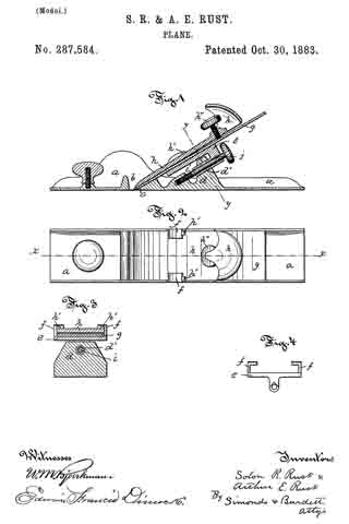
Figure 1 is a view in longitudinal vertical section of a plane embodying our improvements on plane denoted by line x x of Fig. 2. Fig. 2 is a top view of the same. Fig. 3 is a detail view in cross-section on the line y y of Fig. 1. Fig. 4 is a detail end view of the carriage, looking from below.
Our invention has for its object the construction of planes cheaper and more readily adjusted to varied uses than the forms now in common use; and it consists in the special arrangement and combination of the parts for adjusting the cutting-iron and clamping the same, and in changing the character of the plane from a single to a double iron, as hereinafter more particularly described.
In the accompanying drawings, the letter a denotes a body of common form, and made of any desirable material, as iron; b, the usual mortise or opening through to the face of the plane; c, the cutting-bed; d, a transverse flange provided with the socket d’; e, a carriage having upon the lower side a tubular projection adapted to fit into and move longitudinally in the socket d’, and on its upper side the arms f, provided with the interiorly-projecting flanges or their equivalents.
On the carriage, and between the arms, rests the cutting-iron g, which is a flat piece of metal provided with a chisel-edge, and upon it, and also adapted to slide between the arms, is arranged the cap-iron and clamp h, which has upon each side the projections h’, which limit the forward movement of the clamp, and at its rear end, in a threaded socket, the clamp-screw h”.
The screw spindle i is rotarily secured in the tubular projection on the carriage, as by means of the transverse pin j, and its lower end projects into and operates in the nut formed in the body of the plane. This peculiar arrangement of the carriage enables it to have a rocking motion sidewise, or transversely of the plane, and at the same time makes it adjustable in the plane of the cutting-iron. This rocking motion of the carriage enables one to adjust the back of the plane-iron to a perfect bearing on the cutting-bed, and at the same time support and hold it against longitudinal motion.
The cap-iron is made to serve as a clamp by its lower edge, resting upon the cutting-iron near its lower end, passing under the flanges on the arms, which serve as fulcrums, and by being raised from the cutting-iron near the upper end by means of the clamp-screw, the lower end of which takes against the face of the iron. It serves the purpose of the ordinary cap-iron, when desired, and at the same time can be readily slipped back, leaving the plane in the form known as “single-iron” planes.
One peculiar and important feature of our invention consists of the combination of cap-iron and clamp, so arranged that the relative positions of the cutting-edge of the iron and the front edge of the clamp are not changed when the iron is adjusted to fix the thickness of shaving to be cut by the plane. The smoothness of the surface left after removing a shaving is determined by this relative position of cutting-edge of iron and edge of cap-iron, and once fixed in our device it remains constant, as described, while the thickness of the shaving may be varied by the adjustment of the carriage. This construction of parts is a great saving in expense over the ordinary method of arranging and combining the cutting-iron and the cap-iron, and possesses the further advantage of simplicity and ready adjustment to various uses.
The thickness of the shaving made by the plane is adjusted by means of the screw-spindle, which has a suitable head for operating with the thumb and finger.
In order to enable the tubular projection to slide readily, or to rock in the socket d’, we slab off, as seen in Fig. 3, portions of its upper surface, to decrease the bearing-surface within the socket. This, however, is not essential to the perfect operation of our device, as the carriage may have a downward projection resting in a guide-groove in the plane-body, or be adapted to rock in many ways obvious to the skilled mechanic on slight inspection of our device.
We claim as our invention —
1. In combination, a plane-body having a socket, and the carriage having at longitudinal reciprocation and also an transverse rocking motion in said socket, with means for adjusting said carriage, all substantially as described.
2. In combination, the plane-body, the carriage having a longitudinal motion and also a transverse rocking motion, and bearing the plane-iron and combined cap-iron and clamp, all substantially as described.
3. In combination with a plane-body and a carriage, substantially as hereinbefore described, the plane-iron and combined cap-iron and clamp, made, in one piece, the relative position of the two latter parts remaining unchanged when the plane-iron is adjusted to determine the depth of cut of the iron, all substantially as described.
SOLON R. RUST.
ARTHUR E. RUST.
Witnesses:
A. C. TANNER,
WM. H. MARSH.