
| PLEASE NOTE: The images presented on this page are of low resolution and, as a result, will not print out very well. If you wish to have higher resolution files then you may purchase them for only $2.95 per patent by using the "Buy Now" button below. All purchases are via PayPal. These files have all been cleaned up and digitally enhanced and are therefore suitable for printing, publication or framing. Each zip package contains all the images below (some packages may contain more), and purchased files can be downloaded immediately. |
UNITED STATES PATENT OFFICE.
_________________
HENRY B. BEACH, OF MERIDEN, CONNECTICUT.
PLANE.
_________________
SPECIFICATION forming part of Letters Patent No. 287,612, dated October 30, 1883.
Application filed June 21, 1883. (No model.)
_________________
To all whom it may concern:
Be it known that I, HENRY B. BEACH, a citizen of the United States, residing at Meriden, in the county of New Haven and State of Connecticut, have invented certain new and useful Improvements in Planes; and I do hereby declare the following to be a full, clear, and exact description of the invention, such as will enable others skilled in the art to which it appertains to make and use the same.
My invention relates to improvements in bench or block planes; and the object is to improve and simplify their construction, to dispense with the ordinary clamping-iron, and form of the shaving-turning iron the clamping-plate, to be adjusted by a screw through the upper surface and bearing against the bit or cutting-iron, a fulcrum-point being also formed on said shaving-turning iron or clamping-plate, which bears against the cross-bar formed on the body or frame of the plane.
The invention consists in the construction and arrangement of parts, as will be more fully described hereinafter, and more specifically pointed out in the claims, reference being had to the accompanying drawings and the letters of reference marked thereon.
Like letters of reference indicate like parts in the different figures of the drawings, in which —
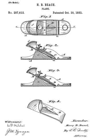
Figure 1 represents a plan view of my plane. Fig. 2 is alongitudinal section of the same on the line x x. Fig. 3 is a longitudinal section, showing the clamping-plate provided with the fulcrum-point. Fig. 4 is a perspective view of the turning-iron.
In the accompanying drawings, A is the body or frame of the plane, cast with the ordinary opening, a, for the plane-iron or bit, and at the upper side with a cross-bar, b, as also with a lug, c, having its upper surface provided with a concave. Upon this lug the plane-iron or bit B rests, and is held in place by the shaving-turning iron C. This is provided with an elongated point or lug, d, as shown in Fig. 1, although it may be rounded off, as indicated by the dotted lines in the same figure, and as also seen in Fig. 4. This point d bears against or under the cross-bar b, when the screw e is set down against the plane-iron or bit, and forms a fulcrum against it. By screwing down the screw e, the point of the shaving-turner is firmly and evenly forced against the entire width of the bit, thus preventing shavings from getting between the bit and turning-iron and clogging it.
In Fig. 3 the clamping-plate D is provided with a similar fulcrum-point, d, which bears against the cross-bar b, as described above, and this plane is more especially adapted for block-planes, in which no shavings are to be turned out of the way.
A cap, f is cast on the turning-iron or clamping-plate, to prevent the hand coming in contact with the end of the bit or plane-iron. Said cap is shown and claimed in another application filed April 4, 1883, attached to a clamping-plate, and claimed therein.
The advantages of attaching the fulcrum-point to the shaving-turning iron or clamping-plate will be apparent to those skilled in the art, and among them are that a much longer fulcrum-point can be obtained. By adjusting the shaving-turning iron against the cross-bar on the frame, the lower point can be clamped much tighter and closer against the plane-iron or bit, and the shavings are turned out of the way without clogging the plane, the necessity of a strong screw-driver for adjusting the shaving-turner against the bit is obviated, and the screw with a milled head is easier to operate and to get at, and the cost of the plane is also greatly reduced.
The old clamping-plate can be used by inserting a lug with point in the elongated slot, as new employed.
I am aware that a central bearing-point has been attached to the cross-bar on the frame, and a clamping-plate adjusted against it by a thumb-screw; but said clamping-plate was plane, and could not form a shaving-turning iron, and I therefore disclaim such.
I am aware of the Patent No. 144,823, granted to Baldwin, also Patent No. 7,565, granted to Traut and Richards, as well as No. 279, 885, granted to Rust, and disclaim the construction therein shown; but
Having thus described my invention, what I claim, and desire to secure by Letters Patent, is —
1. In a plane, the clamping-iron provided with central elevated ridge or point bearing against a bar secured to the body of the plane, so that in adjusting said iron. it will bear uniformly on the planing-iron, substantially as shown and specified.
2. In a plane, the clamping-iron provided with central elevated ridge or point bearing against the lower side of a transverse bar secured to the body of the plane, and adjusted by a screw bearing against the plane-iron, and uniformly pressing against said plane-iron at its lower end, to form a, shaving-turner, substantially as set forth.
In testimony whereof I hereby affix my signature in presence of two witnesses.
HEHRY E. BEACH.
Witnesses:
L. F. KELEHER,
J. M. YZNAGA.