
| PLEASE NOTE: The images presented on this page are of low resolution and, as a result, will not print out very well. If you wish to have higher resolution files then you may purchase them for only $2.95 per patent by using the "Buy Now" button below. All purchases are via PayPal. These files have all been cleaned up and digitally enhanced and are therefore suitable for printing, publication or framing. Each zip package contains all the images below (some packages may contain more), and purchased files can be downloaded immediately. |

UNITED STATES PATENT OFFICE.
_________________
SOLON R. RUST AND ARTHUR E. RUST, UF PINE MEADOW, CONNECTICUT, ASSIGNORS TO SAID
SOLON R. RUST, AND HENRY B. BEACH AND JOHN C. BEACH, BOTH OF MERIDEN, CONNECTICUT.
JOlNER’S PLANE.
_________________
SPECIFICATION forming part of Letters Patent No. 288,866, dated November 20, 1883.
Application filed September 10, 1883. (No model.)
_________________
To all whom it may concern:
Be it known that we, SOLON R. RUST and ARTHUR E. RUST, of Pine Meadow, county of Litchfield, State of Connecticut, have invented an Improvement in Joiners’ Planes, of which the following is a specification.
This invention relates to an improvement in that class of joiners’ planes in which the stock is constructed from metal, usually cast-iron.
In the more general construction of this class of planes the bed to which the plane-iron is clamped is arranged in guides or bearings formed in the sides of the stock. These require to be planed with great exactness, and the bed to be correspondingly fitted.
The object of our invention is to simplify the construction of the plane, so far as the fitting and guiding of the bed are concerned; and it consists in the arrangeinent of a guiding stud or studs in the stock, midway between its two sides, and on an incline corresponding to the inclined position required for the bed, which stud or studs serve as guides for the support and movement of the bed, and having cornbined therewith an adjusting-screw arranged in a plane parallel with the said stud or studs, and as more fully hereinafter described.
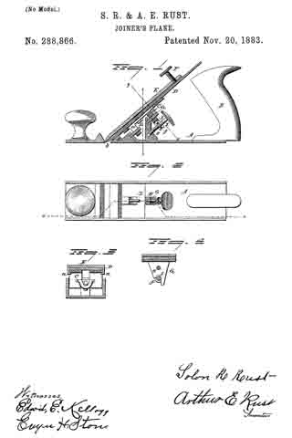
In the accompanying illustration, which forms part of this specification, Figure 1 represents a longitudinal section on line z z; Fig. 2, a top view; Fig. 3, a transverse section on line x x, and Fig. 4 a transverse section on line y y.
A represents the stock, of the usual form, provided with a handle, B. C is the bed on which the iron D rests, and is clamped by means of the cap E, the cap E provided with lugs as near its upper end, which pass under and embrace the bed, as seen in Fig. 3, the set-screw F serving to bring the point of the cap onto the iron near its edge, and so as to clamp the iron firmly to the bed; but this arrangement of clamping is immaterial to this invention, as the cap may be applied in any of the usual or well-known methods.
In the stock beneath the bed a stud, G, is arranged in a plane parallel with the position required for the bed. This stud is best set by drilling into the stock and setting a stud of the required diameter therein, as seen in Fig. 1. On the under side of the bed is a lug, H, at right angles to the bed, and through which a hole is bored corresponding to the stud G, and so as to pass thereon and move freely toward or from the mouth of the plane, the stud serving as a guide for such increment of the bed. This stud, placed centrally, as seen in Fig. 4, permits the bed to rock iroin right to left to adapt itself to the position of the plane-iron. The plane-iron, near the mouth b, takes a bearing on the stock, as at d, which gives the proper transverse position for the plane-irons. The bed will therefore adapt itself to this position of the stud. The lug H extends below the pivot and engages with an adjusting-screw, I. This adjusting-screw is threaded to tit a corresponding screw-hole, e, in the stock, and in a plane parallel with the axis of the stud G. This screw is provided with a collar, f, which engages a slot, l, in the lug H, and so that turning the screw in one direction forces the bed and the iron to more downward, and in the opposite direction upward, and whereby the edge of the iron may be set in the proper relation to the face of the plane. The stud G may be of sufficient length to take a bearing near the two ends of the bed, but we prefer to introduce a second stud, L, into the stock below, as seen in Fig. 1, for the support of the bed below; or two studs may be introduced, one parallel with the other and in the same plane horizontally, which will give two supports for the bed; but in such arrangement of studs the advantage of the rocking movement is not attained.
The introduction of the diagonal guiding-studs into the stock beneath the bed is much cheaper than the usual inclined side guides formed upon the inner surface of the sides of the stock.
What we claim as our invention is —
In a metal plane, the combination of the stock provided with one or more inclined studs, G, beneath the bed, the bed constructed with a. downwardly-projecting lug, H, constructed to ride on said stud as a support and guide, a screw arranged in the stock parallel with said stud and in engagement with the bed, the plane-iron, cap, and means, substantially such as described, for clamping the plane iron to the bed, all substantially as described.
SOLON R. RUST.
ARTHUR E. RUST.
Witnesses:
GEO. H. RICE,
EDW. E. KELLOGG.