
| PLEASE NOTE: The images presented on this page are of low resolution and, as a result, will not print out very well. If you wish to have higher resolution files then you may purchase them for only $2.95 per patent by using the "Buy Now" button below. All purchases are via PayPal. These files have all been cleaned up and digitally enhanced and are therefore suitable for printing, publication or framing. Each zip package contains all the images below (some packages may contain more), and purchased files can be downloaded immediately. |
UNITED STATES PATENT OFFICE.
_________________
ARTHUR T. GOLDSBOROUGH, OF WASHINGTON, DISTRICT OF COLUMBIA.
BENCH-PLANE.
_________________
SPECIFICATION forming part of Letters Patent No. 293,863, dated February 19, 1884.
Application filed July 19, 1883. (No model.)
_________________
To all whom it may concern:
Be it known that I, ARTHUR T. GOLDSBOROUGH, a resident of the city of Washington and District of Columbia, have invented certain new and useful Improvements in Metallic Bench-Planes, of which the following is a specification.
The nature of this invention relates to improvements in construction and arrangement of metallic bench-planes, the object of which is to reduce the number of working parts, and by promoting extreme simplicity of form to reduce the weight, cost, and liability to disarrangement of the several elements of which the tool is composed.
It consists in forming the stock in which the bit and its adjusting-screw are mounted with guiding and retaining cleats arranged in the same line as that of the bit, and between which it moves, and also with a projection near the throat on a somewhat higher line, and over which the bit is forced by its adjusting-screw when being brought to the cutting-point, which operation springs it slightly out of line, securely locking it against the several projections mentioned and hereinafter more fully described.
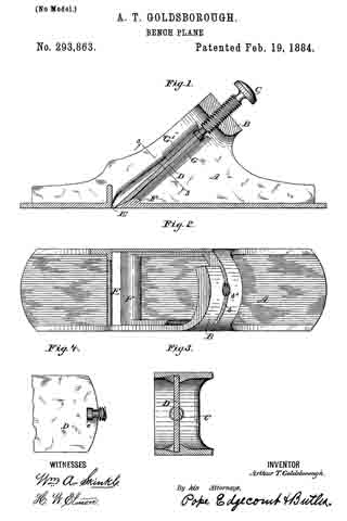
In the accompanying drawings, Figure 1 is a longitudinal section in elevation of a plane, illustrating my invention. Fig. 2 is a plan view of the stock, a portion thereof being broken away to show the cleats and projection or deflector. Fig. 3 is an inverted plan view on line 3 3 of Fig. 1. Fig. 4 is a detail view of parts of the bit and its adjusting-screw.
Similar letters denote like parts.
A represents the stock, which may be of metal, wood, or any other suitable material, but is preferably made of cast-iron.
B is the bridge, formed integral with the stock, and, being at the extremity of the path of the bit, it supports the adjusting-screw C, and also unites the two sides of the stock. The bridge is provided with a slit, b, through which the bit D is inserted and withdrawn; and it also has the threaded aperture b’, which carries the adjusting-screw G. The bit D is formed with a T – shaped slot at its upper end, and the screw C has a corresponding terminal, c, which is T- shaped in cross-section, so that the screw and bit are, when associated together, at all times detachably connected.
E is the throat, the rear interior edge of which is thickened or raised, so as to form the projection or deflector F.
G is a cleat, preferably forming an extension of the material of the stock, and it extends from the under side of the bridge to the deflector, terminating below the highest part thereof, and serving as a guide to direct the course of the bit when being inserted, so that the cutting-edge shall not come in contact with the deflector, but only the beveled under side of the bit.
G’ is a cleat extending about one-third the distance from the under side of the said bridge toward the throat, and parallel with the other cleat, G, with sufficient space between the two to allow the bit to pass freely up and down.
The operation of my device is as follows: The bit is placed in the slot d and moves freely down between the cleats until its beveled under side reaches and rests upon the deflector F, when its downward passage will be arrested. The screw C, having been connected to the bit when it was inserted, is now turned and the bit forced downward. Being held between both cleats at its upper portion only, the edect of this will be to spring the bit forward and obliquely upward, to enable it to pass over the deflector until its edge reaches the operative point, when the said bit will be tightly held between the highest point of the deflector and the short upper cleat, G’.
It will be readily seen that the deflecting device may consist of short cleats or projections attached to the side of the stock, near instead of at the throat of the plane, and they may also be placed above as well as below the bit, if found desirable.
Having described my invention, I claim —
1. A bench-plane having a single bit, and means for moving the same longitudinally, and a stock provided with fixed projections arranged in the path of the cutting-bit, but on different lines, between which projections the bit is held when forced to its operative point, as set forth.
2. A bench-plane having a single bit and detachably-connected adjusting-screw, and a stock formed with cleats, between which said bit. moves freely, and a deflector at or near the throat, over which the bit is forced to its operative point by its adjusting-screw, and between which deflector and cleats it is securely held, substantially as set forth.
3. In a beneh-plane, the stock A, formed with a guiding-cleat extending from the point of insertion of the bit to and terminating at a deflector or raised portion at or near the throat, and a cleat arranged above and parallel to and only a portion of the length of the said guiding-cleat, between which short cleat and the defleetor a cutting-bit may be securely held.
4. In a bench-plane, the combination, with the stock A, provided with slotted and screw-threaded bridge B, uniting the sides thereof, cleats G and G’, extending inward from the sides of the slot, and deflector or projection F, at or near the throat of the plane, of the bit D and detachable adjusting-screw C, all constructed and operating substantially as shown and described.
In testimony whereof I have hereunto subscribed my name this 19th day of July, A. D. 1883.
ARTHUR T. GOLDSBOROUGH.
Witnesses:
FRANKLAND JANNUS,
FRANK P. WHITE.