

| PLEASE NOTE: The images presented on this page are of low resolution and, as a result, will not print out very well. If you wish to have higher resolution files then you may purchase them for only $2.95 per patent by using the "Buy Now" button below. All purchases are via PayPal. These files have all been cleaned up and digitally enhanced and are therefore suitable for printing, publication or framing. Each zip package contains all the images below (some packages may contain more), and purchased files can be downloaded immediately. |
UNITED STATES PATENT OFFICE.
_________________
JUSTUS A. TRAUT, OF NEW BRITAIN, CONNECTICUT.
BENCH-PLANE.
_________________
SPECIFICATION forming part of Letters Patent No. 294,825, dated March 11, 1884.
Application filed October 17, 1883. (No model.)
_________________
To all whom it may concern:
Be it known that I, JUSTUS A. TRAUT, a citizen of the United States, residing at New Britain, in the county of Hartford and State of Connecticut, have invented certain new and useful Improvements in Bench-Planes, of which the following is a specification.
My invention relates to improvements in bench-planes. In my improved plane I combine a beading and center-beading tool, plow, dado, fillister and rabbet, matching-tool, and slitting-tool.
The objects of my improvement are to render the combined tool simple in construction and convenient to change from one form to another, and to improve its working in many particulars when changed. I attain these objects by the construction illustrated in the accompanying drawings, in which —
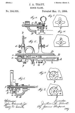
Figure 1 is a side elevation of my tool arranged for use as a plow. Fig. 2 is a plan view thereof. Fig. 2A is a vertical section of detached parts on line z z of Fig. 2. Fig. 3 is a side elevation, showing the reverse side of said plow as compared with Fig. 1. Fig. 4 is a vertical section of the same on line x x of Fig. 1. Fig. 5 is a reverse plan view of my plane arranged for use as a matching-tool. Fig. 6 is a vertical section thereof on line y y of Fig. 5. Fig. 7 is a side elevation of a detached portion of the stock, showing the adjustable spur. Fig. 8 is a like view of the same as set in a different position, so as to throw the spur out of action; and Figs. 9 and 10 are like views of a modified form of the same.
My convertible or combination tool consists of three principal parts — viz., the two parts of the stock and the gage or fence. These parts are found in a prior patent to myself, dated March 4, 1873, and the changes herein described in those parts may be considered in the nature of an improvement upon the plane shown in said patent.
I make the parts A and B of the double stock mainly of cast metal, and with thin steel blades on at secured thereto. These I prefer to let into a rabbet upon the inner faces of the parts A B, and with a dovetailed or overhanging upper surface for said rabbet, the upper edges of the blades being correspondingly formed, as shown in Figs. 4 and 6. I secure these blades to the parts A B by means of screws or rivets b. The lower edges of these blades, upon their inside corners, may be beveled off, as shown, in order to adapt the blades for use in connection with a beading-cutter. By thus making the blades or lower edges of the stock of steel, the stock may be made much lighter than a cast-iron stock, while at the same time it is stronger. I am also enabled to make said blades rnuch narrower, and thereby I adapt the device for use with a much narrower cutter than has heretofore been practical. In fact, they may be made so thin as to adapt the tool for use with a cutter only one-
eighth of an inch in width.
As in prior implements of this class, the part A of the stock is provided with gage or fence rods C, for connecting and adjusting the two parts of the stock, and also for adjusting and holding the gage or fence D in proper position relatively to the stock. Instead, however, of providing this fence with only one set of holes for the rods C, I provide two sets of holes or sockets, c, and I arrange the fastening-screw d’ intermediate between said two holes or sockets, as shown most clearly in Figs. 1 and 2A, and I slightly bevel the end of the set-screw d’, so that it will impinge upon the rod C and hold the same, whether it bein the upper or lower one of the sockets c. This construction of the fence enables it to be placed higher up on the stock for certain uses, as shown in Figs. 1, 3, and 4, or so as to come lower down relatively to the bottom of the stock, as shown in Fig. 6.
I have herein illustrated the cutters d e as held in place by means of the clamp-bolt f as shown and described in my prior patent, before referred to; but any other ordinary clamping mechanism may be substituted therefor.
Upon the outside vertical faces of the blades a a, at any suitable point thereon, but preferably a little in front of the throat, as shown in Fig. 3, I arrange spurs g, for use in connection with a plow or dado, the uses of such spurs being well known. I place these spurs in a circular depression so located with reference to the edge of the stock that it runs out at the lower edge. The spur proper is formed as a radial arm of a thin steel hub or disk, having a pivotal screw, h, passed through its center into the center of the circular recess in the sides of the blades a a. I prefer to form upon this rotary spur three other arms, as shown, two of which act in connection with a stationary stop, i. By loosening the screw h, the spur may be thrown so as to project directly downward from the bottom of the stock, in which position it is stopped by contact of one of the arms with the stop i, as shown in Figs. 3 and 7, in which position it may be held by tightening the screw h. The stop, however, in connection with the pivotal screw h, is in such position as to receive the thrust or working-strain which comes upon the spur g in driving the tool forward, so that it is only necessary to tighten the screw h suffiiciently to prevent the spur from working out of place when the plane is drawn backward. When it is desired to throw the spur wholly out of action, it is only necessary to loosen the screw and turn the spur forward until another one of the arms strikes the stop i, as shown in Fig. 8, when the screw may be tightened sufficiently to hold the rotatory spur in said position. If desired, all four of the arms on this spur-disk may be sharpened, so that by loosening the screw far enough to let the arms slip by the stop, either of said arms may be brought downward so as to proiect below the lower edge of a, whereby a sharp and fresh cutting-spur can he brought into action in case the one first set in position for action by any means becomes impaired.
In Figs. 9 and 10 I have shown a modification of the spur-disk, and the manner of holding it in the stock. Instead of the circular recess before described, I sink a star-shaped depression or recess in the side of the stock, the lower part of which recess, as in the former case, extends to the lower edge of the stock. The spur-disk is substantially the same as before, except that I either make one short arm or make only three arms to radiate from the hub. I employ the same central fastening-screw; but instead of the stop i being formed separately in the form of a pin, and subsequently secured to the stock, the eccentric shape of the edge of the recess enables the walls thereof to perform the function of a stop to prevent the spur from rotating in either direction.
In order to set the spur g’ in position tor action, it is placed so as to extend downward and project below the bottom face of the stock, as shown in Fig. 9; or in case all of the arms are sharpened, the spur-disk may be set with either of its arms extended downward, as may be desired. In order to throw the spur out of action, it is only necessary to loosen the screw enough to let the spur-disk come forward out of the recess — that is, out of engagement with its stop — and then partially revolve on the central screw, so as to bring the short arm or side having no arm toward the bottom face of the stock, and then drop the spur-disk into its recess and tighten the screw, as shown in Fig. 10. In like manner the spur-disk may be changed to bring either arm of the spur into action.
E, Figs. 2, 3, and 5, designates a depth-gage of ordinary construction, and consequently a description is unnecessary.
F designates a slitting-knife vertically adjustable within a suitable seat upon the part A of the stock, for use in connection with a plow-stock substantially as shown and described in the patent to Rappleye, No. 266,519, October 24, 1882. In connection with this slitting-knife I employ another depth-gage, G, Figs. 3 and 5, and fasten the same in place by the same screw and nut which secure the slitting-knife F. I have shown the depth-gage E as placed in the main part A of the stock, (said part being that which carries the handle and rods C C;) but I provide the sliding part B of the stock with a socket, k, and set-screw m, as shown in Fig. 2, to receive and hold said gage when desired.
Having described the general construction of the parts, I will now describe the manner of using my improved plane tor the several purposes hereinbefore named. For all of these various uses, except in using the plow with a very narrow cutter, both parts of the stock are used together, and it is not necessary that any of the parts hereinbefore described shall remain detached for using my plane as any of the foregoing-named tools, except the dado, and for beading in the middle of a wide surface.
In order to use my plane as a beading and center-beading tool, I insert and fasten the proper-shaped cutter, bringing the two parts of the stock together, and placing the depth-gage in the part A of the stock, the fence or gage D being preferably set with the rod C in the lowest sockets, so as to bring the gage at the highest point, as shown in Fig. 4. If the bead is to be formed at a distance from the edge of the board greater than that to which the gage may be adjusted, said gage will have to be removed and a suitable strip fastened upon the board to gage by, the same as with other beading-tools. For beading crosswise with the grain, the spurs g should be thrown into cutting action.
For use as a plow, a cutter is selected of a desirable width and clamped in place, the two parts of the stock brought together, the depth-gage properly adiusted, the fence D being secured as shown in Fig. 4, and the spurs g brought into position for acting. By placing the gage for the plow higher up with reference to the bottom of the stock, instead of lower down, as shown in Fig. 6, it can be made to gage the work much more properly, and to steady the plow against tipping over sidewise, because it will bear against the edge of the surface of the work to its extreme upper edge, even after the cutters have plowed to a considerable depth , whereas with a gage set low down, as shown in Fig. 6, that portion of the edge surface of the work which is above the lower end of the cutter is also above the top edge of the gage, so that said portion of the surface can furnish no support whatever against the tool tipping over sidewise. The broken lines in Fig. 4 indicate a piece of work that has been plowed a distance about equal to half the depth of the gage D, and shows the relative position of the gage and stock thereto.
If a cutter is to be used whose width is less than that of the combined thickness of the blades a a, the removable part B of said stock and its blades a must be removed. The remaining part A may then be used with a cutter of practically the same width as the thickness of the blade a.
For a dado, the fence or gage D is wholly removed, a suitable cutter is inserted in place, and the two parts of the stock brought together, the depth-gage E is secured and properly adjusted within the sliding part B of the stock, and the spurs g set for cutting action.
For a fillister and rabbet, a cutter of the desired width is selected and properly secured within the stock, the depth-gage is placed in the part A of the stock, and the fence or gage D secured by passing the rods C through the upper sockets of said gage, as shown in Fig. 6.
For a slitting-tool, the knife F is properly adjusted and the tool used in the manner set forth in the patent to Rappleye hereinbefore specified. The bottom gage, G, may also be used in connection therewith, if desired. This gage may also be brought down into position for use when the slitting-knife is drawn upward or removed, if desired, and while the other depth-gage, E, is placed in the sliding part D of the stock, thereby bringing a depth-gage into action upon both sides of the stock, for use in connection with any of the several tools.
The cutter d (shown in Figs. l, 2, and 3) is an ordinary cutting-bit with an edge square across the end.
The cutter e (shown in Figs. 5 and 6) is one which is specially adapted for a matching-tool, and is provided with a depth-gage, a, secured directly to the cutter. This cutter is shown herein merely to show my plane as adapted for a matching-tool, and said cutter and its gage I intend to make the subject of another application of even date herewith.
In lieu of the gage n, other gages may be arranged to bear upon the edge of the tongue for gaging the depth.
I employ a matching-tool having a narrow shank with a wider bit at its cutting end, so that when its narrow shank is set in position and the two parts of the stock brought against the respective edges thereof the cutting-edge of the bit will project laterally upon both sides of the stock, at the bottom part thereof, as shown in Figs. 5 and 6.
The gage or fence D is placed in its lowermost position, so that it may slide under the cutting-edge of the cutter and bottom edge of the stock, as shown in Fig. 6. This enables me to adjust the gage to a point from the middle of the cutter a distance equal to half the thickness of the board to be tongued, and when so adjusted the tongue formed on the board by this matching-tool will always be exactly in the middle, and this can be accomplished with the use of only one cutter in any board whose thickness is not greater than the width of the cutter at its lower end, and which is not so narrow as the space between the blades a a, or, in other words, the longitudinal groove in the bottom face of the stock. By thus making the cutting end of the cutter wider than the span of the blades a a or working-face of the stock, I can with a single cutter centrally tongue boards of different thicknesses within the limits before named.
I claim as my invention —
l. The combination of the gage-rods C C of a bench-plane, the gage or fence D, having two sets of sockets-one above the other-and suitable means for fastening said gage upon said rods, substantially as described, and for the purpose specified.
2. The combination of gage-rods C C, a suitable gage or fence having double sockets for the reception of said rods, and a set-screw arranged intermediately between the sockets and adapted to clamp the rods when placed in either one of the sockets, substantially as described, and for the purpose specified.
3. The combination of the stock and the rotatory cutting-spur adapted to project below the edge of the stock, or to be carried up above said edge by turning it upon its axis, substantially as described, and for the purpose specified.
4. The combination of the stock, the rotatory spur pivoted thereto, and a suitable stop for limiting the rotation of said spur during the forward movement of the stock, substantially as described, and for the purpose specified.
5. The combination of the stock, the spur-disk having radial arms, the adjusting-screw, by means of which said disk is secured to the stock, and a suitable stop for preventing said spur-disk from rotating on said screw, substantially as described, and for the purpose specified.
JUSTUS A. TRAUT.
Witnesses:
JAMES SHEPARD,
JOHN EDWARDS, Jr.