
| PLEASE NOTE: The images presented on this page are of low resolution and, as a result, will not print out very well. If you wish to have higher resolution files then you may purchase them for only $2.95 per patent by using the "Buy Now" button below. All purchases are via PayPal. These files have all been cleaned up and digitally enhanced and are therefore suitable for printing, publication or framing. Each zip package contains all the images below (some packages may contain more), and purchased files can be downloaded immediately. |
UNITED STATES PATENT OFFICE.
_________________
JACOB SIEGLEY, OF WILKES-BARRE, PENNSYLVANIA.
BENCH-PLANE.
_________________
SPECIFICATION forming part of Letters Patent No. 294,919, dated March 11, 1884.
Application filed July 6, 1883. (No model.)
_________________
To all whom it may concern:
Be it known that I, JACOB SIEGLEY, of Wilkes-Barré, Luzerne county, and State of Pennsylvania, have invented certain new and useful Iinproveinents in Bench-Planes, of which the following is a specification.
This invention has reference to certain improvements in bench-planes for which Letters Patent have been granted to me heretofore, which Letters Patent bear date. respectively, July 1, 1879, August 16, 1881, and January 2, 1888, and are numbered 216,979, 245,752, and 269,988, the improvements being designed with a view to cheapen the manufacture, increase the usefulness of the plane, and facilitate the handling of the same.
The invention consists of a bench-plane in which the fixed and movable blades are provided with advance cutters, which are inserted into sidewise-inclined perforations of said blades, and secured thereto by clamp-screws, so that the lower ends of the advance cutters project somewhat beyond the planes of the blades. The stock of the blade is provided with sockets cast integral therewith, for the purpose of receiving lateral guide-rods, which are made of one piece and clamped in said sockets by means of set-screws. The front part of the stock has a horizontal slot for the purpose of receiving the rim of a screw-nut, which engages the threaded shank of a stop-gage, said shank being guided in suitable holes arranged in the stock, while the stop-gage is guided in a recess of the laterally-adustable cage or fence.
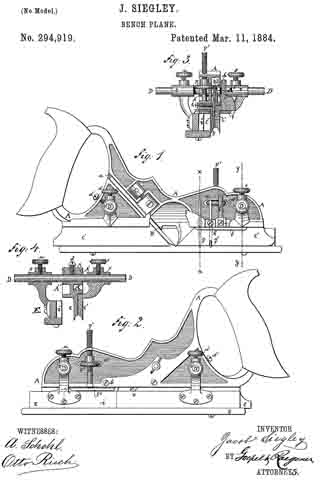
In the accompanying drawings, Figures 1 and 2 are side views, showing both sides of my improved plane. Fig. 3 is a vertical transverse section on line x x, Fig. 1. Fig. 4 is a similar section on line y y of the same figure.
Similar letters of reference indicate corresponding parts.
Referring to the drawings, A represents the stock of my improved bench-plane, which is made of cast-iron or other suitable metal, and provided with a handle of the usual form at the rear end. The middle part of the stock A is provided with an inclined recess, a, in which a cutting tool or plow, B, of any required width is guided and locked in any approved manner, preferably by the means shown in Letters Patent No. 269,968, dated January 2, 1883. Along the lower part of the stock is arranged a fixed blade, C, while a second movable blade, C’, is arranged sidewise of and parallel to the fixed blade C, as will be shown hereinafter. Each of these blades C and C’ contains a laterally-inclined perforation that extends from the upper to the lower part of each blade, so that the lower end of the perforation opens partly at the outer side and partly at the bottom of its respective blade, as shown in Figs. 1 and 8. The advance cutters g and g’ are attached into said perforations by means of set-screws it It in such a manner that the cutting-edge of each cutter projects slightly at the side and lower edge ofthe blades C and C’, thereby providing a better clearance in the work for the plow. The stock A is provided at its front and rear part with openings and sockets A A’, that project at both sides of the same, for the purpose of receiving the guide-rods D and D’, which are made of one continuous piece and of the same thickness throughout, and secured in said sockets by means of set-screws d d’. Larger and smaller guide-rods D D are furnished with each plane, so as to adjust the movable blade C’ at one side and a fence, E, at the other side of the stock, to a greater or smaller distance from the same. On one side of the stock these guide-rods pass through the sleeves r and r’, which are cast in one piece with the blade C’, and secured by means of set-screws s s’. The sleeves and the blade C’ can be adjusted to various distances from the blade C, according to the width of the plow B. At the opposite sides of the stock A the guide-rods D D’ pass through sleeves t t’‘, which are attached to the gage or fence E. The sleeves t t’ are provided with set-screws u u’, for the purpose of laterally adjusting the gage E as the nature of the work may require. A horizontal slot, a2, is cut in the front part of the stock A, for the purpose of receiving the rim of the screw-nut F, which engages the threaded shank F’ of a stop-gage, F2, so as to raise or lower the same on turning the serew-nut F in one or the opposite direction. The shank F’ is guided in suitable holes arranged in the flanged stock A. The stop-gage F2 can thus be adjusted by means of its screw-shank and nut to any desired depth. The blade C’ is also furnished with a stop-gage, f, that is guided in a socket and secured by means of a setscrew, f’. The gage or fence E is provided with a, recess, i, for the stop-gage F2, so as not to interfere with the same, even when the gage E is placed close to the blade C of the stock A.
Having thus described my invention, I claim as new and desire to secure by Letters Patent —
1. In a bench-plane, the combination of the fixed and adjustable blades C C’, each having a laterally-inclined perforation, with advance cutters g g’ and clamp-screws h h’, the advance cutters projecting at their lower ends slightly beyond the outer side plane of the blades C C’, substantially as set forth.
2. In a bench-plane, the combination of the stock A, having a horizontal slot, a2, at its front part, a stop-gage, F2 the threaded shank of which is guided holes of the stock, and a screw-nut, F, the rim of which is engaged by the slot a2, so that the screw-nut F raises or lowers the stop-gage on being turned in one or the opposite direction, substantially as described.
3. In a bench-plane, the combination of the stock A., having a horizontal slot at its front part, a stop-gage, F2, the threaded shank of
which is guided in holes of the stock, an adjusting screw-nut, F, the rim of which is engaged by the slot a2, and a gage or fence, E, having a side recess, i, for the stop-gage F2 substantially as set forth.
In testimony I claim the foregoing as my invention I have signed my name in presence of two subscribing witnesses.
JACOB SIEGLEY.
Witnesses:
CARL KARP,
SIDNEY MANN.