
| PLEASE NOTE: The images presented on this page are of low resolution and, as a result, will not print out very well. If you wish to have higher resolution files then you may purchase them for only $2.95 per patent by using the "Buy Now" button below. All purchases are via PayPal. These files have all been cleaned up and digitally enhanced and are therefore suitable for printing, publication or framing. Each zip package contains all the images below (some packages may contain more), and purchased files can be downloaded immediately. |
UNITED STATES PATENT OFFICE.
_________________
CHARLES A. MEEKINS, OF NEW HARTFORD, CONNECTICUT.
BENCH-PLANE.
_________________
SPECIFICATION forming part of Letters Patent No. 295,414, dated March 18, 1884.
Application filed May 31, 1883. (No model.)
_________________
To all whom it may concern:
Be it known that I, CHARLES A. MEEKINS, of New Hartford, in the county of Litchfield and State of Connecticut, have invented a certain new and useful Improvement in Bench-Planes, of which the following is a description, reference being had to the accompanying drawings, where —
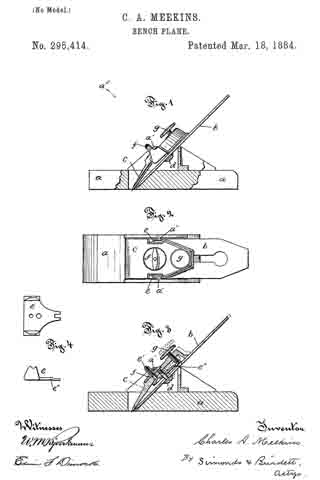
Figure 1 is a side view, with a portion of the sides of the stock represented as broken away. Fig. 2 is a view looking diagonally down upon the top from the point a5 over Fig. 1. Fig. 3 is a view of the plane in central vertical lengthwise section. Fig. 4. shows a detail top view of the rocking clamp-iron, and also a detail side view of the same.
The letter a denotes the stock or body of the plane, which may he partly of wood and partly of metal, or substantially wholly of wood or wholly of metal. In the drawings I show it with the bottom part composed of wood and the upper part of iron.
The letter b denotes the chisel or plane-iron, of the ordinary kind. The letter c denotes the cap-iron, which is novel in its construction; but it is secured to the plane-iron b, in substantially the ordinary way, by the connecting-screw d.
The letter e denotes what I call the “rocking clamp-iron,” because it has a rocking motion for effecting the adjustment of the plane-iron and cap-iron on the studs or pivots a’ a’; and it also serves in a novel manner the function of a clamp-iron-that is, it is the important factor in attaching the plane-iron and the cap-iron to the stock of the plane. This rocking clamp-iron runs under the cap-iron. The pin e’, jointed somewhat loosely at the bottom to the rocking clamp-iron, projects upward through the cap-iron, and upon the upper end bears the nut f, by means of which the plane-iron and cap-iron are clamped to the stock — that is, by running the nut down, the journal ends of the rocking clamp-iron press against the studs a’ a’, and the plane-iron is forced firmly down upon its seat. This rocking clamp-iron has an extended part or lever end, e”, the end of which is bifurcated, and takes hold of an annular groove in the adjusting-screw g, which is hung in the cap-iron.
By manipulating this adjusting-screw the edge of the plane-iron may be nicely adjusted. The mode or manner in which this is effected is not, perhaps, plain at a first glance; but the explanation is that by manipulating this adjusting-sorew the clamp-iron is rocked on pivots a’, and carries the plane and cap irons with it in its up and down but not its rocking movements.
I claim as my improvement —
1. In combination, the plane-body bearing the pivots, the plane-iron, the cap-iron attached to the plane-iron, the longitudinally-rocking clamp-iron, adjustably connected to the cap-iron and bearing between its points of connection upon the pivots on the plane-body, all substantially as described.
2. The oornbination of the longitudinally-rocking clamp-iron e, loosely attached to cap-iron e by pin e’ and nut f, adjusting-screw g, plane-iron b, and plane-body a, with pivot-bearings for the clamp-iron, all substantially as described.
CHARLES A. MEEKINS.
Witnesses:
SARA J. SIMONDS,
WM. E. SIMONDS.