
| PLEASE NOTE: The images presented on this page are of low resolution and, as a result, will not print out very well. If you wish to have higher resolution files then you may purchase them for only $2.95 per patent by using the "Buy Now" button below. All purchases are via PayPal. These files have all been cleaned up and digitally enhanced and are therefore suitable for printing, publication or framing. Each zip package contains all the images below (some packages may contain more), and purchased files can be downloaded immediately. |
UNITED STATES PATENT OFFICE.
_________________
AMOS FALES, OF DENVER, COLORADO.
VARIABLE BENCH-PLANE.
_________________
SPECIFICATION forming part of Letters Patent No. 295,916, dated April 1, 1884.
Application filed March 31, 1883. (Model.)
_________________
To all whom it may concern:
Be it known that I, AMOS FALES, of Denver, in the county of Arapahoe and State of Colorado, have invented certain Improvements in Variable Bench-Planes; and I do hereby declare that the following is a full and exact description thereof, reference being had to the accompanying drawings, making part of this specification.
These improvements are upon variable bench-planes constructed upon the general plan set forth in Letters Patent granted to me March 7, 1882, No. 254,542, and are mainly additional thereto, although I have in one or two respects changed and improved the construction therein shown and described. Except as to these changes, as hereinafter specified, I use the invention substantially as described in the said Letters Patent; but it is to be understood that the improvements herein described and claimed may be applicable to other constructions of bench-planes besides those therein set forth; and my invention is intended to embrace all applications to which the several features, any or all, may be adapted.
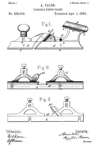
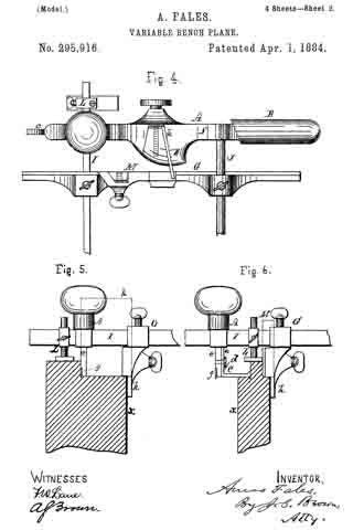
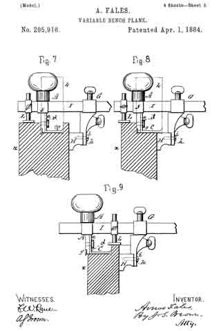
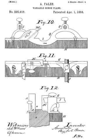
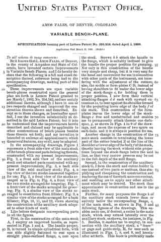
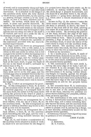
In the accompanying drawings, Figure 1 represents a front side view of the main stock of the bench-plane and parts belonging thereto, constructed with my present improvements, Fig. 2, a front side view of the auxiliary stock and attached parts constructed with my present improvements 5 Fig. 3, a back side view of the said auxiliary stock; Fig. 4, a top view of the two stocks connected together for use; Fig. 5, a front view of the stocks arranged as in Fig. 4; Fig. 6, a front view of the two stocks arranged for tonguing; Fig. 7, a front view of the stocks arranged for grooving; Fig. 8, a similar view of the stocks arranged to constitute a front fillister; Fig. 9, a similar view of the stocks arranged for a back fillister; Figs. 10, 11, and 12, views showing the construction of the auxiliary stock adapted to other kinds of work.
Like letters designate corresponding parts in all the figures.
First, in the construction of the main stock A, I employ an improved handle, as represented in Figs. 1 and 4. The handle proper, B, is turned in simple cylindrical form, with one side slightly flattened to rest upon a straight plane-surfaced flange, a, cast upon the stock. Screws b b attach the handle to the flange, which is suitably inclined to give the handle the proper position for grasping. Not only is this construction of the handle very simple and cheap, but it is very easy for the hand and convenient for use in connection with other parts of the instrument, not interfering with the adjustment of the cutters; also, the molds or form-plates C D, instead of having shoulders to fit under the lower edge of the stock-flange c, for holding them in proper position, I now form their vertical attaching-flanges d d each with upward extensions e e, to bear against the shoulder formed by the projecting lower edge of the body f of the stock. This construction of the form-plates leaves the lower edge of the stock-flange c free and unobstructed and enables me to permanently attach thereto one dado-spur, g, as shown in Figs. 4 to 9 of the drawings, and saves the expense of two spurs on each dado. and it is always in position for use.
Another change in the construction of the main stock consists in terminating the lower part of the cutter-bracket E at the line of the shoulder or lower edge of the body f of the stock, thereby leaving the stock without side projections beyond the stock-flange below the said line, so that very narrow grooves may be out to the full depth of the said flange.
Second, in the construction of the auxiliary stock G, I form the stock and cutter-holder in one instead of two parts or sections, thus simplifying and cheapening the construction and rendering the use ofthe stock more convenient, and enabling me to apply any other attachment which may be desired. The stock thus approximates in construction and use to the main stock.
Further, for many purposes the fiange h of the auxiliary stock extends lower than or entirely below the corresponding flange, c, of the main stock, as shown in Fig. 5 and following figures of the drawings. This enables me to use, if desired, a cutter in the main stock, which may extend laterally over the auxiliary stock, as shown, for instance, in Fig. 5. Besides, it enables me to employ, in connection with the auxiliary stock, a “fence” or gage and guide-strip, H, for uses such as illustrated in Figs. 7, 8, and 9, and hereinafter set forth. This fence is preferably made of wood, and is consequently cheap and light. It is made of the form shown or any other most convenient. It is attached to the flange h of the auxiliary stock below the body thereof, which forms a guide-shoulder, by two screws, i i passing through notches j j of the stock-flange, so that it is easily attached and detached. Its surface, which faces the main stock, is plane and parallel therewith. By adjusting the auxiliary stock to the required distance from the main stock on the connecting-bars I J this fence may be brought to bear against and run along one side of the stuff to be worked, and serve as a guide for the instrument and gage for the work.
In Figs. 4 and 5 and the following figures of the drawings I illustrate the operation of the instrument provided with the above-de-
scribed improvements.
In Figs. 4 and 5 is shown an arrangement for a front fillister, with a wide cutter, k, in the main stock overlapping the auxiliary stock, which in this case needs no cutter, but is low enough in the middle to allow the lapping over of the main-stock cutter. The flange h furnishes the side gage, and the vertical gage-stop L is mounted on the connecting-bar I, back of the main stock, to gage the depth of the cut in the board or stuff x, indicated by dotted lines in Fig. 5.
In Fig. 6 is shown an arrangement for tonguing. Here also the flange h of the auxiliary stock serves as the side gage, and the vertical gage-stop is mounted between the two stocks. The cutter k of the main stock cuts behind the tongue of the board x, and a cutter, M, in the auxiliary stock cuts in front of the tongue.
In Fig. 7 I show an arrangement for grooving. In this arrangement a fence, H, is used on the auxiliary stock for the side gage, and the vertical gage-stop I is arranged back of the main stock, the cutter k of the main stock cutting the grooves in the board or plank x, in connection with the fixed dado-spur g on the main-stock flange.
In Fig. 8 is shown an arrangement for a front fillister, with the use of a fence, H, on the auxiliary stock. By this arrangement as narrow a rabbet or shoulder may be cut in the stuff as ever will be required.
In Fig. 9 is shown an arrangernent for a back fillister, a fence, H, on the auxiliary stock furnishing the side gage, and the vertical gage-stop L being mounted between the two stocks.
Figs. 10, 11, and 12 show a construction of the auxiliary stock adapted to kinds of work in which it is not convenient for the flange h to project lower than the main stock — as, for instance, in making window-sashes. Here the stock-flange h projects horizontally, and the fence H is attached below it, the attaching-screws i i going down through notches j j, which allow a lateral adjustment of the fence.
As seen in Fig. 12, the screws i i enter the fence nearer one edge than the other. When the fence is attached, as shown, the fence is back of the front side of the stock, allowing the cutter M of the stock to cut over the sash x or other article. By reversing the position of the fence, however, the edge of the same projects in front of the stock, as required for some kinds of work. There is a notch or depression, l, Figs. 10 and 11, in the middle of the auxiliary stock, to allow the center of the main stock to reach over the auxiliary stock, when desired. The auxiliary stock is depressed under this notch, the fence being cut away to allow the two to come together.
I claim as my invention —
1. In a bench-plane, a handle, B, made of cylindrical form, flattened on one side, in combination with an inclined plane-faced flange, a, on the plane-stock. substantially as and for the purpose herein specified.
2. The combination of the main stock A, having the lower edge of its body f and cutter-bracket E in one straight line, and its flange c provided with a dado-spur, g, and the form-plates C D, having vertical attaching-flanges d d bearing against the straight lower edge of the said stock-body and bracket, and adapted to have their lower surfaces flush with the lower edge of the said stock-flange, substantially as and for the purpose herein specified.
3. The reversible fence H, in combination with the stock G, the points of attachment being to one side of the middle longitudinal line of the fence, whereby two positions are given thereto fulfilling two purposes, substantially as herein specified.
4. The combination of the main stock A, having a downwardly-extended flange, c, on its lower edge, and a cutter extending laterally beyond the stock, and the auxiliary stock G, cut away at the top to allow the main-stock cutter to project over it, and having a flange, h, bent laterally, substantially as and for the purpose herein specified.
In testimony whereof I have signed my name in presence of two witnesses.
AMOS FALES.
Witnesses:
J. DEWEESE,
H. T. CASTLE.