
| PLEASE NOTE: The images presented on this page are of low resolution and, as a result, will not print out very well. If you wish to have higher resolution files then you may purchase them for only $2.95 per patent by using the "Buy Now" button below. All purchases are via PayPal. These files have all been cleaned up and digitally enhanced and are therefore suitable for printing, publication or framing. Each zip package contains all the images below (some packages may contain more), and purchased files can be downloaded immediately. |


UNITED STATES PATENT OFFICE.
_________________
GEORGE D. MOSHER AND WILLIAM H. FORD, OF BIRMINGHAM, CONN.
JOINER’S PLANE.
_________________
SPECIFICATION forming part of Letters Patent No. 296,207, dated April 1, 1884.
Application filed January 21, 1884. (No model.)
_________________
To all whom it may concern:
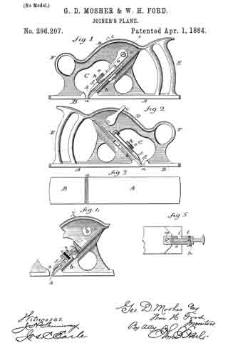
Be it known that we, GEORGE D. MOSHER and WILLIAM H. FORD, of Birmingham, in the county of New Haven and State of Connecticut, have invented a new Improvement in Joiners’ Planes; and ive do hereby declare the followiing, when taken in connection with accompanying drawings and the letters of reference marked thereon, to be a full, clear, and exact description of the same, and which said drawings constitute part of this specification, and represent, in —
Figure 1, a left-hand side view; Fig. 2, a right-hand side view, Fig. 3, a face view; Fig. 4, a sectional side view, to illustrate the adjustment of the cutter, Fig. 5, a section on line x x, looking downward, to show the connection between the cutter and the hub of the adjusting-lever.
This invention relates to an improvement in planes for joiners’ use, particularly to that class in which the stock is constructed from cast metal.
The principal object of the invention is to construct the stock with the mouth and throat extending entirely across it, and whereby the possibility of “choking” is avoided; but it also has for its object a simple and easy adjustment of the cutter; and the invention consists in the construction, as hereinafter fully described, and more particularly recited in the claims.
A represents the rear portion, and B the front-portion, between which the mouth a is formed. This mouth extends entirely across the face of the plane, as seen in Fig. 3, instead of leaving a connection between the front and rear portions at each end of the mouth, as in the usual construction. As the front and rear parts of the stock are separated by this mouth, We connect them above and over the throat C by a connection, D, extending from the handle E at the rear to a handle, F, at the front. This connection is made in the form of a thin web centrally on the stock, so as to make the plane as light as it conveniently can be. The back of the throat is inclined to form a seat, b, for the cutter d in the usual relation to the mouth. From the seat b a standing screw-threaded stud, e, extends forward at right angles to the seat, over which the cutter will set, the cutter being constructed with a slot for such purpose, and so as to permit the cutter to be moved up or down, as occasion may require. The cutter placed thereon, a cap or clamping piece, f, is applied over the bolt, and then a nut, h, turned thereon, clamps the cutter to its seat. This stud e is best fixed in place by being introduced into the mold and the metal cast around it.
As a simple and convenient means for adjusting the cutter, we arrange a lever, i, upon a hub, l, which extends through the web, and so as to take a seat therein and permit the hub to be turned by applying the fingers to the lever. The handle stands upon one side of the web, as seen in Fig. 5.
On the cutter, above the stud e, is a stud, m. From this stud a link, o, extends up to the hub l on the opposite side to the lever i, and is there connected to the hub by an eccentric pin or screw, p, as seen in Fig. 5. Therefore by turning the lever i the eccentric pin p imparts a corresponding movement to the link, and thence to the cutter, so that turning in one direction the cutter may be drawn upward, or in the opposite direction forced downward, according to the adjustment required.
By this construction of plane the throat and mouth are open from side to side, so that the cuttings or shavings must readily pass out of the throat, and cannot by any possibility be stopped therein, so as to choke the mouth. The adjustment of the cutter is simple and cheap.
We are aware that metal planes have been constructed with the mouth extending from side to side in like manner as in what are known as “rabbet-planes,” and therefore do not claim, broadly, such a plane.
We claim —
1. A cast-metal plane having the front and rear portions separated by the mouth and throat, whereby said mouth and throat are open from side to side, the front and rear portions connected over the throat, the rear portion constructed vvith a seat, b, for the cutter, said seat provided with a fixed screw-threaded stud, e, the cutter d, the clamp f, and nut h, substantially as described.
2. A cast-metal plane having the throat and mouth open from side to side, the rear and front portions of the stock connected centrally centric connection with the hub of said lever, over the throat above the cutter, the rear portion constructed with a, seat to receive and support the cutter, the adjusting-lever i, arranged above the cutter in the connection which unites the rear and front portions, and a link in connection with the cutter and in eccentric connection with the hub of said lever, substantially as described.
GEORGE D. MOSHER.
WILLIAM H. FORD.
Witnesses:
EDWIN B. GAGER,
ANDREW J. EWEN.