
| PLEASE NOTE: The images presented on this page are of low resolution and, as a result, will not print out very well. If you wish to have higher resolution files then you may purchase them for only $2.95 per patent by using the "Buy Now" button below. All purchases are via PayPal. These files have all been cleaned up and digitally enhanced and are therefore suitable for printing, publication or framing. Each zip package contains all the images below (some packages may contain more), and purchased files can be downloaded immediately. |
UNITED STATES PATENT OFFICE.
_________________
JOSEPH B. RIPSOM, OF OSHKOSH, WISCONSIN.
PLANE.
_________________
SPECIFICATION forming part of Letters Patent No. 296,785, dated April 15, 1884.
Application filed July 21, 1884. (No model.)
_________________
To all whom it may concern:
Be it known that I, JOSEPH B. RIPSOM, a citizen of the United States, residing at Oshkosh, in the county of Winnebago and State of Wisconsin, have invented a new and useful Plane, of which the following is a specification, reference being had to the accompanying drawings.
This invention relates to carpenters’ planes, and is especially adapted for use as a carriage-maker’s miter-plane. Its object is to provide a plane possessing superior advantages in point of simplicity, inexpensiveness, durability, and general efficiency.
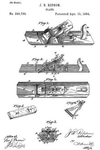
In the drawings, Figure 1 is a perspective view of my improved plane. Fig-2 is a vertical longitudinal sectional view of the same. Fig. 3 is a vertical transverse sectional view taken on the line x x, Fig. 2. Fig. 4 is a top view of the plane with the bit, cap-plate, and eccentric lever removed. Fig. 5 is a detail perspective view of the bit. Fig. 6 is a detail perspective view of the cap-plate.
Referring to the drawings, A designates the stock, which is formed of metal and provided with the usual handle, B. This stock comprises a bottom plate, C, at the side edges of which are provided longitudinal flanges D D, that incline outwardly and upwardly from plate C at an angle, preferably, of forty-five degrees. The throat or slot E extends entirely across the plate C, so that the bit or cutter extends to the vertex of the angles formed by plate C and flanges D D. A transverse brace-plate, F, is preferably formed between the flanges D D and just in front of the throat E, while a transverse rib, G, is provided some distance in rear of the throat, and is formed with a screw-threaded recess, H. Between this rib G and the throat E are provided upright side danges I I, having perforations J, in which a cross-pin, K, is secured.
L is a lever-block, which is provided with an elongated perforation, M, at its front end, through which passes a fulcrurn-screw, N, into the recess H, and has also upright side flanges, O O, at this end, formed with perforations P. At the rear end of this lever-block is formed a screw- threaded perforation, Q, through which works a set-screw, R, against the bottom plate, C, to raise and lower the said lever, by which operation the bit can be set at different angles for convenience in cutting with or across the grain of the wood.
S is a bed-plate, which is provided with a longitudinal slot, T, having longitudinal side shoulders, U U, and also has downwardly-extending side flanges V V, formed with perforations W, through which a cross-pin, X, is passed to pivot the bed-plate to the lever-block. The bed-plate extends down between the flanges I I, and a set-screw, Y, works through the slot T, with its head against the shoulders U U, into a block or nut, Z, bearing against the under side of the bed-plate. The head of this set-screw engages a cross-slot, A2, in the bit or cutter B2, to retain the latter in position, and the screw is only to be moved as the cutter wears away.
C2 is a cap-plate, which is preferably formed of steel, and is bowed to form a spring, as shown. This plate is preferably formed with end shoulders, D2 D2, which engage corresponding shoulders, E2 E2 at each side the throat E.
F2 is an eccentric lever, comprising an operating-handle, G2, and an eccentric head, H2, formed with a transverse groove, l2, by which it can be engaged under the pin K, to bind against the spring-plate and secure the bit in position against the bed-plate.
The operation and advantages of my invention will be readily understood and appreciated. It is very sirnple and efiicient in construction, and its parts can be easily governed and adjusted. By turning the set-screw R the bit will be given cut, and when the screw is turned back the tension of the spring cap-plate will automatically return the bit to its former position.
I claim as my invention —
1. The combination, with the stock comprising the bottom plate having the longitudinal side flanges inclined outwardly and upwardly at an angle from the bottom plate, and formed with the throat extending entirely across the bottom plate to the vertex of the angle formed by the bottom plate and side danges, of a lever-block fulcrumed on the stock, a set-screw for operating the said lever, a bed-plate connected with the lever, the bit carried by the bed-plate, and means for securing the bit in position, substantially as set forth.
2. The combination of the stock having the throat and upright flanges, the cross-pin between the latter, the lever-block having the fulcrum-perforation, and disposed just above the bottom plate and in rear of the throat, the fulcrum-screw, the set-screw for adjusting the lever, the longitudinally-slotted bed-plate pivoted on the lever, the set-screw working in the slot in the bed-plate, the bit having the slot for receiving the head of this screw, the spring cap-plate, and the eccentric lever under said cross-pin and acting to clamp down the spring cap-plate, substantially as and for the purpose set forth.
3. The combination, in a plane, of the main bottom lever, the set-screw working through the free end of the lever, a bed-plate pivoted to the lever at its fulcrurn end, the bit or cutter connected with the bed-plate, the bowed spring cap-plate, the cross-pin K, and the eccentric lever adjustable under this pin and against the springplate, whereby the bit can be adjusted by the set-screw and will be returned by the said spring-plate, substantially as set forth.
4. The combination of the bed-plate having the longitudinally-disposed slot formed with longitudinal side shoulders, the set-screw working through the slot with its head against the shoulders, the nut receiving the screw and bearing against the under side of the bed-plate, and the bit having the transverse slot that received the head of the set-screw, the bit being carried and adapted to be fed by adjusting said screw, substantially as set forth.
5. The combination of a bed-plate, the bit or cutter connected thereto, the bowed spring cap-plate, the cross-pin K, and the eccentric lever having the eccentric head formed with the transverse slot, substantially as and for the purpose set forth.
In testimony that I claim the foregoing as my own I have hereto aftixed my signature in presence of two witnesses.
JOSEPH B. RIPSOM.
Witnesses:
JOHN BAUMGARTNER,
GUSTAV EILERS.