
| PLEASE NOTE: The images presented on this page are of low resolution and, as a result, will not print out very well. If you wish to have higher resolution files then you may purchase them for only $2.95 per patent by using the "Buy Now" button below. All purchases are via PayPal. These files have all been cleaned up and digitally enhanced and are therefore suitable for printing, publication or framing. Each zip package contains all the images below (some packages may contain more), and purchased files can be downloaded immediately. |

UNITED STATES PATENT OFFICE.
_________________
NORMAN EDWARD CURTIS, OF MAUSTON, WISCONSIN.
BENCH-PLANE.
_________________
SPECIFICATION forming part of Letters Patent No. 296,933, dated April 15, 1884.
Application filed January 28, 1884. (Model.)
_________________
To all whom it may concern:
Be it known that I, NORMAN EDWARD CURTIS, of Mauston, in the county of Juneau and State of Wisconsin, have invented a new and Improved Bench-Plane, of which the following is a full, clear, and exact description.
In the class of bench-planes having adjustable plane-irons it is common to adjust the plane-iron longitudinally by means of an adjusting screw and lever, and to clamp the plane-iron and its cap by means of a clamping-lever provided with a cam.
My invention provides means for the accurate and quick lateral adjustment of the plane-iron, and it consists in a fulcrum upon which the plane-iron may swing laterally, a longitudinal groove formed in the rear face of the iron, and a lever fulcrumed in the lower part of the plane, with its shorter arm entering the groove in the back of the plane-iron, and its longer arm extending rearward, to be operated by hand or by an adjusting-screw.
Reference is to be had to the accompanying drawings, forming a part of this specification, in which similar letters of reference indicate corresponding parts in all the figures.
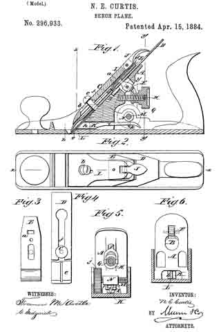
Figure 1 is a vertical longitudinal section of my improved plane, taken on the line x x in Fig. 2. Fig. 2 is a plan view. Fig. 3 is a detail view of the cap-iron. Fig. 4 is a rear view of the plane-iron. Fig. 5 is a vertical transverse section taken on the line y y y in Fig. 1. Fig. 6 is a vertical transverse section taken on the line z z in Fig. 1, the irons being removed.
The body of the plane is of the usual form, having the bed-piece A attached thereto in the usual way. In the upper surface of the bed-piece A is formed a groove, B, of sufficient width and depth to receive the screw C, which clamps the plane-iron D and cap-iron E together. The groove B is of sufficient length to permit the greatest required range of longitudinal rnovement of the plane-iron, while it embraces the sides of the screw-head so closely as to admit of little or no lateral motion of the plane-iron at that point. The shorter arm of a lever, F, fulcrumed in the bed-piece A, extends into an aperture, a, in the cap-iron E. The longer arm of the lever F is engaged by a milled nut, G, on the screw-threaded stud H, projecting from the back of the bed-piece A. By turning the milled nut G the plane-iron D is adjusted longitudinally in the usual way. The plane-iron D and cap-iron E are clamped in place by a clamping-lever, I, having a slot bolt hole, b, near its lower end for receiving the screw c, which also passes through the plane-iron and the cap-iron. A cam-lever, J, pivoted in the upper end of the clamping-lever, presses on a bearing plate, d, carried by the lever I, and which, in turn, presses upon the upper end of the cap-iron. The lever I is similar to others in use; but lf have shortened the distance between the screw c and the lower end thereof, and have increased the distance between the said screw and the cam-lever J, so as to secure an increased leverage and a corresponding increase in the firmness with which the plane-iron is held in place.
In the back of the plane-iron D and from the lower end thereof along the middle a groove, e, extends toward the usual longitudinal slot, f, of the plane-iron.
In a mortise formed in the lower portion of the bed-piece A a lever, K, is fulcrumed, so as to swing in a plane parallel with the face of the plane-body. The shoulder-arm h of the lever K is beveled and provided with a tongue, L, entering the groove e in the back of the plane-iron D. The longer arm i of the lever K, extends beyond the rear of the bed-piece A, where it may be moved by the hand alone or by any suitable mechanical device. I prefer to employ a screw, M, journaled transversely in the plane-body, and having a milled head, j, and carrying a traveling nut, N, having a loop, k, for receiving the longer arm i of the lever K. By turning the screw M in one direction or the other the lever K is correspondingly moved, and the plane-iron, by virtue of its engagement with the lever, is swung laterally, the clamping-screw C being the center of motion. This adjustment enables the user to readily and accurately adjust the cutting-edge of the plane-iron to parallelism with the face of the plane; and, furthermore, the tongue L at the end of the lever K forms a guide which permits of replacing the plane-iron in the plane-body without the necessity of special adjustment each time it is removed and replaced. Where a single iron is used, a screw corresponding to the clamping-screw C will be inserted in the back thereof to form a pivot on which the iron may swing.
I have described one term of my invention. It is obvious that it adrnits of various modifications, such as substituting a rib for the groove in the back of the iron and making a groove for its reception in the end of the adjusting-lever. The adjusting-lever may be bifurcated and made to embrace the edges of the plane-iron when neither the groove nor the rib would be required. It will also be seen that the adjusting-screw may be arranged to act directly on the plane-iron to secure the necessary lateral movement. In view of these various possible modifications of my improvement, I do not limit or confine my invention to the precise form herein shown and described.
Having described my invention, I claim as new and desire to secure by Letters Patent —
1. In a bench-plane, the combination, with the pivoted plane-iron having in its lower rear side a longitudinal groove of the laterally-adjustable lever adapted to fit into the groove of the plane iron, and capable of adjustment by the hand, substantially as and for the purpose set forth.
2. In a bench-plane, the combination, with the longitudinally-grooved bed-piece, of the cap-iron having the rear headed projection or screw, with its head entering the groove of said bed-piece, and the adjusting-lever engaging said iron, and actuated by an adjusting-nut, substantially as and for the purpose set forth.
3. In a bench-plane, the combination, with the pivoted plane-iron having in its lower rear surface a longitudinal groove, of the laterally-adjustable lever having a tongue entering the groove of the plane-iron, and the headed screw carrying a nut or sleeve provided with a loop which receives the outer end of the aforesaid lever, substantially as and for the purpose set forth.
NORMAN EDWARD CURTIS.
Witnesses:
JOHN F. CURTIS,
GEORGE CURTIS.