
| PLEASE NOTE: The images presented on this page are of low resolution and, as a result, will not print out very well. If you wish to have higher resolution files then you may purchase them for only $2.95 per patent by using the "Buy Now" button below. All purchases are via PayPal. These files have all been cleaned up and digitally enhanced and are therefore suitable for printing, publication or framing. Each zip package contains all the images below (some packages may contain more), and purchased files can be downloaded immediately. |


UNITED STATES PATENT OFFICE.
_________________
JOHN A. KEISER, OF CINCINNATI, OHIO, ASSIGNOR TO SAMUEL C. TATUM & CO., OF SAME PLACE.
CABINET-SHAVE.
_________________
SPECIFICATION forming part of Letters Patent No. 300,266, dated June 10, 1884.
Application filed February 28, 1884. (No model.)
_________________
To all whom it may concern:
Be it known that I, JOHN A. KEISER, a citizen of the United States, and a resident of Cincinnati, in the county of Hamilton and State of Ohio, have invented certain new and useful lmprovements in Cabinet-Shaves, of which the following is a specification.
My invention relates to an improved cabinet-shave, and other similar tools.
The object of my invention is to provide ready means for removing or inserting the bit or knife, all of which will be fully set forth in the description of the accompanying drawings.
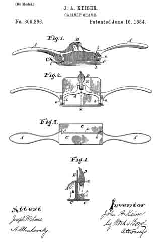
Figure 1 is a perspective view of my invention with the bit removed. Fig. 2 is a front elevation of my improvement with the bit in position for use. Fig. 3 is a bottom plan view of Fig. 2. Fig. 4: is a vertical section on line x x, Fig. 2.
A A represent the handles of my improved shave.
B represents the central portion of the stock of the shave, which, with the handles, is preferably made of malleable iron, cast in one piece. a represents ears cast on and with the stock B.
C represents the swiveling or detachable bit-face; C’, the stationary bit-face, which forms a part of the stock B.
b represents ears attached to the face C, and provided with pivots i, which hinge the ears b to the ears a.
d represents a yoke or bar connected to the ears b.
The parts C, b, b, and d are made of metal formed in one piece, and arranged so as to more freely upon the pivots i.
D represents a cam connected by pivot c to the center of the yoke d.
E represents the bit or knife, which is made to fit into the head B, as shown in Figs. 2 and 4. In order to hold the knife in position by detachable fastenings, it is essential to have it gripped at two points — first, at or near the cutting edge, and, second, at the central point of the knife, sufficiently near the upper end to prevent its rocking or moving. To accomplish this I provide lugs h, at each end of the cutter E on the bottom of face C, and adapted to bear against the cutter E upon each side of the shaving-slot L.
The mode of operation in inserting the knife is as follows: Fig. 1 represents the device with knife or bit removed from the stock of the shave and the cam D hanging loosely upon the yoke d. The knife E is inserted with the proper feed, (the edge depending below the faces C C’,) and cam D is turned upward so as to bring the shoulder against the face ofthe knife. This movement draws the lugs h, on the face C firmly against the blade E, pressing or gripping it tightly against the face C’ of the stock by the inward movement of the face C, caused by the pressure of the shoulder of cam D against the upper end of the knife, forcing the yoke d outward. This mode of constructing the stock and attaching the parts holds the knife firmly in position, and yet allows it to be instantly inserted and removed.
The principal feature of my invention consists in constructing the pivoted portion of the stock so as to grip the knife near the cutting-edge, and central at or near its upper end, and at the same time not be apt to become accidentally disconnected from its bearings.
An inferior modification of my invention would be to employ a thumb-screw passing through the yoke d, instead of the cam D, for gripping the upper end of the knife E. Such a construction would be covered by the first and second claims herein. Spokeshaves and other tools could be made in a similar manner as the within-described cabinet-shave. Another modification could be made by having the lugs h, attached to the face C’ and the shaving-slot in the same side of the bit-face. So, too, one lug h might be employed near the center of the bit-plane; but it would not be as efficient as the plan here shown.
I claim —
1. A shave composed of the stock B and bit-face C’, in combination with the bit-face C, swiveled by a pintle placed parallel with the axis of rotation of the bit-face, and a fastening device, D, suitably supported, and adapted to grip the bit at or near the top and force one of the bit-faces against the lower edge of the bit, whereby the bit will be held to its place by said fastening D and bit-face, independently of other fastenings, substantially as described.
2. The combination, with the stock B and stationary bit-face C’, of the bit-face C, provided with lugs h to bear against the bit and with yoke d, and swiveled by a pintle parallel with its axis of rotation, and a fastening device, D, connected with the yoke d and adapted to bear against the upper part of the bit, the bit being held to its place by said fastening D and the face C, independently of other fastenings, substantially as described.
3. The combination of the stock B and stationary bit-face C’, provided with ears a, the bit-face C, provided with ears b and yoke d, and swiveled to ears a by pintles i, and the cam-lever D, fulcrumed on yoke d, for instantaneonsly fastening and releasing the bit, substantially as described.
In testimony whereof I have hereunto set my hand.
JOHN A. KEISER.
Witnesses:
EDWARD BOYD,
ANDREW E. SCOTT.