| PLEASE NOTE: The images presented on this page are of low resolution and, as a result, will not print out very well. If you wish to have higher resolution files then you may purchase them for only $2.95 per patent by using the "Buy Now" button below. All purchases are via PayPal. These files have all been cleaned up and digitally enhanced and are therefore suitable for printing, publication or framing. Each zip package contains all the images below (some packages may contain more), and purchased files can be downloaded immediately. |
UNITED STATES PATENT OFFICE.
_________________
SOLON R. RUST AND ARTHUR E. RUST, OF PINE MEADOW, CONNECTICUT.
PLANE.
_________________
SPECIFICATION forming part of Letters Patent No. 300,399, dated June 17, 1884.
Application filed March 26, 1884. (No model.)
_________________
To all whom it may concern:
Be it known that we, SOLON R. RUST and ARTUR E. RUST, of Pine Meadow, in the county of Litchfield and State of Connecticut, have invented certain new and useful Improvements in Planes; and we do hereby declare that the following is a full, clear, and exact description thereof, whereby a person skilled in the art can make and use the same, reference being had to the accompainying drawings, and to the letters of reference maarked thereon.
Like letters in the figures indicate the same parts.
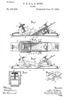
Figure 1 is a view in longitudinal central section of my improved plane. Fig. 2 is a top view of the same. Fig. 3 is a side view of the same. Fig. 4 is a view in cross-section of the adjustable yoke on plane denoted by line x x of Fig. 3. Fig. 5 is a detail perspective view of the carriage which supports the plane-iron.
Our invention relates to the class of planes having a flexible face and means for adjusting the plane-face for working on a convex or concave surface.
It also embraces certain features of construction applicable broadly to planes.
lt consists in the combination of a plane-body with a flexible face and means for adjusting the face, and in the combination of devices for holding and adjustiiig the cutting-iron of the plane-body, as more particularly hereinafter described.
In the accompanying drawings, the letter a denotes the plane~body as a whole,made of any suitable material — as iron — having a bed, a’, through which the plane-iron projects, vertical sides a5, which support the face and the blade-adjusting devices, respectively. The flexible face b is fast to the plane-base, and the forked arms c and d are pivoted to the plane-body, as by means of pivots c’ d’, and to the outer ends of the face, as by means of the links c and f. Each of these levers has a short arm, c2 d2, pivotally connected to each other by rods g, The yoke h is pivoted at its lower end to each arm of the lever c near the pivots c’, and bears between the upper and lower crossbars, h1 h2 , an adjusting-screw, i, which is arranged about centrally of the plane-body in a threaded socket in the cross-piece a2, fast to the plane-body in front of the plane-iron. Any vertical movement of the yoke imparted to it by the adjusting-screw i is transmitted to the lever c, and by means of connecting-rods g to the lever d, and from these levers c d to the opposite extremities of the flexible plane-face. This adjustment of the plane-face may be made to a convex surface, as denoted by dotted lines in Fig. 1, or to a concave with equal ease.
The adjustable carriage k is supported in the plane-body by means of the longitudinal and central bearings, l l’, the former resting upon the cross-bar a2, fast to the plane-body, and the latter in a tubular socket, a1, in the plane-body. The carriage k has the downward-projecting lugs k1 k2, against the inner faces of which bear the opposite ends of an adjusting-screw, m, which moves in a threaded socket in the cross-bar a3, fast to the plane-body. This carriage also has the arms n, with the inward-projecting extremities n’, so arranged as to grasp the upper surface of the clamp-iron o, placed over the iron p upon the carriage, when the parts are in position in the plane-body. The lower end of the clamp-iron bears upon the plane-iron just back of the cutting-edge, and its upper end bears the clamp-screw o’, moving in a threaded socket near the upper end of the clamp, and with its point bears upon the upper surface of the plane-iron. The central bearings of the carriage permit of a lateral motion of the carriage and the supported plane-iron, by means of which the plane-iron may be adjusted to a perfect bearing in the socket in the body. The peculiar method of holding the adjusting-screw between the lugs projecting from the carriage prevents backlash or lost motion of the parts and permits a more careful adjustment.
The plane-body, yoke, and the carriage of our improved plane are made, preferably, of metal — as iron — cast to shape, with threaded sockets and bearings for the adjusting-screws and bearings for the carriage formed in subsequent operations.
The main advantage of our improved device is the low cost of its manufacture and simplicity of the operating parts, which perform the functions attainable in like devices of the prior art only at considerable expense.
The peculiar method of holding the clamping-screw between the lugs on the lower part of the carriage relieves the maker of the tool from exercising any great care to get the bearings for the carriage and the axis for the adjusting-screw parallel, as the opposite ends of the adjusting-screw may have lateral play between the lugs and not render the device inoperative.
The plane may be quickly changed from a single-iron plane to a double-iron plane by sliding back the clamp, and the plane-iron adjusted for cutting without changing the clamp, but by simply turning the adjusting-screw m.
We claim as our invention —
1. In combination, in a flexible face-plane, a plane-body, a, a flexible face, b, levers c d, pivotally connected to the plane-body, to each other by connecting-rod g, and to the flexible face-plate, with means for changing the position of said levers and of the flexible face, all substantially as described.
2. The combination of a plane-body, flexible face, pivoted levers connecting the said face and the body, a yoke, h, pivotally connected to the said levers, and an adjusting-screw, i, having bearings in the yoke and in the plane-body, all substantially as described, and for the purpose set forth.
3. The combination of a plane-body, a, a carriage, k, with the central bearings, l l’, fitted to suitable bearings in the plane-body, and with lugs k1 k2, bearing upon opposite extremities of an adjusting-screw, m, attached to the body, all substantially as described.
4. In a plane, the combination of a plane-body, a, a carriage, k, with central bearings, l l’, projecting lugs k1 k2, and projections w’, an adjusting-screw, m, with its opposite ends bearing on the inner faces of the lugs, plane-iron p, and clamp-iron o, with clamp-screw o’, all substantially as described.
5. In a plane, the combination of a plane-body and a carriage having lugs bearing upon opposite extremities of an adjusting-screw, m, movable in a socket in a plane-body, all substantially as described, and for the purpose set forth.
6. In combination, a plane-body, a, having bed a’, cross-bars a2 a3, and socket a4, the forked levers c d, pivoted to the body, connecting-rods g, yoke h, pivoted to the levers, and adjusting-screw i, with plane-iron p and means for holding the same in the body, all substantially as described, and for the purpose set forth.
SOLON R. RUST.
ARTHUR E. RUST.
Witnesses:
JOSEPH W. DREYRUON,
O. S. THOMPSON.


