
| PLEASE NOTE: The images presented on this page are of low resolution and, as a result, will not print out very well. If you wish to have higher resolution files then you may purchase them for only $2.95 per patent by using the "Buy Now" button below. All purchases are via PayPal. These files have all been cleaned up and digitally enhanced and are therefore suitable for printing, publication or framing. Each zip package contains all the images below (some packages may contain more), and purchased files can be downloaded immediately. |
UNITED STATES PATENT OFFICE.
_________________
T. M. RICHARDSON, OF STOCKTON, MAINE.
DEVICE FOR SECURING PLANE-BITS.
_________________
Specification of Letters Patent No. 30,248, dated October 2, 1860.
_________________
To all whom it may concern:
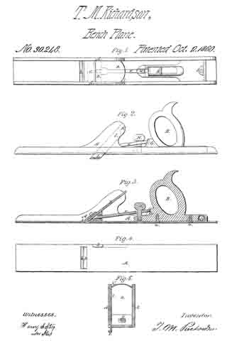
Be it known that I, THEODORE M. RICHARDSON, of Stockton, in the county of Waldo and State of Maine, have invented an Improved Joiner’s Plane; and I do hereby declare that the same is fully described in the following specification and represented in the accompanying drawings, of which —
Figure 1, is a top view; Fig. 2, a side view; Fig. 3, a longitudinal section, and Fig. 4, an underside view of it. Fig. 5, exhibits a transverse section taken through the middle of the slider arranged in the side of the plane stock.
In these drawings A, denotes the stock, and, B, the handle thereof, the two being formed of metal or other suitable material and secured together by screws, a, a. The throat, b, of the plane stock is furnished with a stationary cap iron or cutter bearing, C, against the underside of which the cutter or plane iron, D, is arranged as shown in the drawings. The said plane iron is forced or clamped against the cap iron, C, by means of a wedge, E, a pitman, F, an inclined plane G, and a screw H, arranged relatively to each, the plane stock, the cutter and handle as shown in the drawings, that is to say, the wedge, E, is placed between the cutter and the base plate of the stock, while the inclined plane, G, is disposed in front of the handle and the pitman is made to extend from the inclined plane to the wedge and has the screw, H, carried through it and screwed into the front part of the base of the handle. By screwing down the said screw, the pitman will be forced down the inclined plane and by the latter will be driven forward against the wedge and thereby cause the said wedge to force the cutter or plane iron hard up against the bearing or cap iron, C. A slider, I, is arranged in the side of the plane stock and so as to slide into the recess, K, formed therein, and parallel or nearly so to the cutter. When the said slider is made to extend out of the socket or recess and beyond the lower face of the plane stock as shown in the drawings, it will serve as a guide for a workman in planing a “glue joint” or one surface at right angles to another the slider serving, in this respect, the purpose of an ordinary carpenter’s square, as its inner face, when the slider is extended shall stand at ip right angle with the underside of the stock.
In rear of the handle and in its base, I arrange a small glass spirit level L, and so as to stand transversely with respect to the plane stock, in other words at right angles with its sides, the said level being disposed as shown in Figs. 1 and 3. By this arrangement of the level it is covered and protected by the wrist of a workman while his hand may be grasping the handle, B, and thus the level is not so likely to becoine broken as would be the case were it arranged at the opposite end of the stock and in advance of the handle. My arrangement of the parts for holding the plane iron in place enables such iron to be removed and replaced with respect to the cap iron without requiring the aid of a screw driver or hammer.
I claim —
The arrangement of the clamp wedge E, the pitman, F, the inclined plane, G, and the screw, H, with the plane iron D, its cap bearing, C, and the stock A, substantially as described.
T. M. RICHARDSON.
Wtitnesses:
HENRY S. STAPLES,
ALEXANDER STAPLES, Jr.