

| PLEASE NOTE: The images presented on this page are of low resolution and, as a result, will not print out very well. If you wish to have higher resolution files then you may purchase them for only $2.95 per patent by using the "Buy Now" button below. All purchases are via PayPal. These files have all been cleaned up and digitally enhanced and are therefore suitable for printing, publication or framing. Each zip package contains all the images below (some packages may contain more), and purchased files can be downloaded immediately. |
UNITED STATES PATENT OFFICE.
_________________
WILLIAM F. KELLETT, OF CHICAGO, ILLINOIS.
PLANE-BIT.
_________________
SPECIFICATION forming part of Letters Patent No. 305,393, dated September 16, 1884.
Application filed May 26, 1884. (No model.)
_________________
To all whom it may concern:
Be it known that I, WILLIAM F. KELLETT, a citizen of the United States, and residing at Chicago, in the county of Cook and State of Illinois, have invented a certain new and useful Improvement in Plane-Bits, which is fully set forth in the following specification, reference being had to the accompanying drawings, in which —
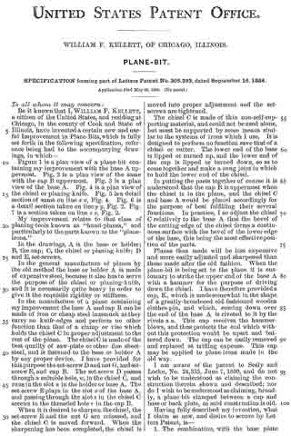
Figure 1 is a plan view of a plane-bit containing my iniprovement with the base A uppermost. Fig. 2 is a plan view of the same with the cap B uppermost. Fig. 3 is a plan view of the base A. Fig. 4 is a plan view of the chisel or planing-knife. Fig. 5 is a detail section of same on line x x, Fig. 4. Fig. 6 is a detail section taken on line y y, Fig. 2. Fig.
7 is a section taken on line z z, Fig. 2.
My improvement relates to that class of planing-tools known as “hand-planes,” and particularly to the parts known as the “plane irons.”
In the drawings, A is the base or holder; B, the cap; C, the chisel or planing-knife; D and E, set-screws.
In the general manufacture of planes by the old method the base or holder A is made of expensive steel, because it also has to serve the purpose of the chisel or planing-knife, and it is necessarily quite heavy in order to give it the requisite rigidity or stiffness.
In the manufacture of a plane containing my improvement the base A and cap B can be made of iron or cheap steel inasmuch as they carry no knife-edges and perform no other function than that of a clamp or vise which holds the chisel C in proper adjustment to the rest of the plane. The chisel C is made of the best quality of saw-plate or other line sheet-steel, and is fastened to the base or holder A by any proper device. I have provided for this purpose the set-screw D and nut G, and set-screw E, and cap B. The set-screw D passes through a suitable hole, w, in the chisel C, and runs in the slot n in the holder or base A. The set-screw E plays in the slot o of the base A, and passing through the slot s in the chisel C screws in the threaded hole r in the cap B.
When it is desired to sharpen. the chisel, the set-screw E and the nut G are released, and the chisel C is moved forward. When the sharpening has been completed, the chisel is moved into proper adjustment and the set-screws are tightened.
The chisel C is made of thin non-self-supporting material, and could not be used alone, but must be supported by some means similar to the systems of irons which I use. It is designed to perform no function save that of a chisel or cutter. The lower end of the base is lipped or turned up, and the lower end of the cap is lipped or turned down, so as to come together and make a snug joint in which to hold the lower end of the chisel.
In putting the parts together of course it is understood that the cap B is uppermost when the chisel is in the plane, and the chisel C and base A would be placed accordingly for the purpose of best fulfilling their several functions. In practice, I so adjust the chisel C relatively to the base A that the bevel of the cutting-edge of the chisel forms a continuous surface with the bevel of the lower edge of the base, this being the most effective position of the parts.
Planes thus made will be less expensive and more easily adjusted and sharpened than those made after the old fashion. When the plane-bit is being set in the plane it is customary to strike the upper end of the base A with a hammer for the purpose of driving down the chisel. I have therefore provided a cap, K, which is made somewhat in the shape of a greatly-broadened old-fashioned wooden clothes-pin, and which, coming down over the end of the base A is riveted to it by the rivets a a. This cap receives the hammer-blows, and thus protects the end which without this protection would be upset and battered down. The cap can be easily removed and replaced at trifling expense. This cap may be applied to plane-irons made in the old way.
I am aware of the patent to Seely and Locke, No. 24,335, June 7, 1859, and do not wish to be understood as claiming the construction therein shown and described; nor do I wish to be understood as claiming, broadly, a plane-bit clamped between a cap and base or back plate, as said construction is old.
Having fully described my invention, what I claim as new, and desire to secure by Letters Patent, is —
1. The combination, with the base plate having the thin steel chisel adjustably connected therewith, the adjacent surfaces of the two being plane surfaces, of the cap connected with the base-plate by a clamp-screw to clamp the chisel rigidly against the back plate, substantially as and for the purposes specified.
2. The combination, with the slotted base-plate, of the chisel connected therewith by a clamp-screw at its upper end, whereby the chisel may be adjusted longitudinally on the base-plate, and of the cap connected with the base-plate by a clamp-screw, whereby the chisel may be firmly clamped against the base-plate, when so adjusted, substantially as and for the purposes specified.
3. The cornbination, with the base A, chisel C, and cap B, provided with the slots o n s, and holes r w, of the set-screw E, and set-screw D, and nut G, substantially as and for the purposes set forth.
4. The combination, with the base A, of the cap K, substantially as and for the purposes set forth.
WM. F. KELLETT.
Witnesses:
G. E. FAULKNER,
LEONARD WATSON.