
| PLEASE NOTE: The images presented on this page are of low resolution and, as a result, will not print out very well. If you wish to have higher resolution files then you may purchase them for only $2.95 per patent by using the "Buy Now" button below. All purchases are via PayPal. These files have all been cleaned up and digitally enhanced and are therefore suitable for printing, publication or framing. Each zip package contains all the images below (some packages may contain more), and purchased files can be downloaded immediately. |
UNITED STATES PATENT OFFICE.
_________________
JOHN A. KEISER, OF CINCINNATI, OHIO.
BENCH-PLANE.
_________________
SPECIFICATION forming part of Letters Patent No. 305,602, dated September 23, 1884.
Application filed June 30, 1884. (No model.)
_________________
To all whom it may concern:
Be it known that I, JOHN A. KEISER, a citizen of the United States, and a resident of Cincinnati, in the county of Hamilton and State of Ohio, have invented certain new and useful Improvements in Bench-Planes, of which the following is a specification.
This invention relates to improvements in benoh-planes; and it has for its object to provide novel and efficient means for adjustably connecting the cutter with the plane-stock. This I accomplish in the manner and by the construction and combination of devices hereinafter described and claimed, reference being had to the accompanying drawings, illustrating my invention, in which —
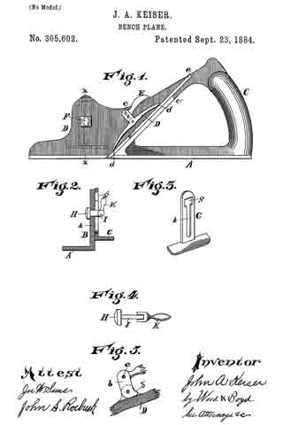
Figure 1 is a side elevation of my improvement. Fig. 2 is a cross-section on line x x, Fig. 1. Fig. 3 is a perspective view of the side gage. Fig. 4 is an enlarged detail view of the side gage and fastening-clamp. Fig. 5 is a detail view of the clamping device.
A represents the base of my plane-stock; B, the side of the stock, G, the handle; c, the ledge on which cutter a rests and is secured.
D represents the cutter-clamp, which is operated as follows:
E represents a bell-crank lever, which is pivoted at e and the side of the stock B.
b represents the arm of bell-crank lever, to which the clamp D is pivotally attached.
b’ represents a shoulder or stop for limiting the pivotal movement of clamp D on arm b, to force the points d down upon the cutter a.
The crank E is made to have two bearing-points, d d. The clamp D is raised and lowered by the movement of the bell-crank lever E. When occupying the position shown in Fig. 1, the clamp D is forced down upon the cutter a, and holds it securely in position. When it is desired to readjust the cutter a, or to take it out, the bell-crank E is lifted up, which moves the points of the clamp away from contact with the cutter a, and allows it to be removed or adjusted.
F represents a mortise or opening pierced through the side of the stock B.
G represents the adjustable side gage, which is provided with a mortise, g, through which is inserted a clamp, and a slot, h, which slides over the shank of the clamp, for allowing the gage G to be adjusted.
H represents a headed clamp-bolt.
I represents the shank of the same, over which the slot h of the gage G moves up or down for its adjustment.
K represents a cam or eccentric lever pivoted to the shank I, which, when turned up, bears against the face of the gage G, securely clamping it in position by drawing the head of clamp-bolt H against the side of the plane-stock, and the cam clamping or pressing against the outside of the gage G. When the lever K is turned down, gage G is released, so that it may be adjusted to the desired height. The mortise g is sufficiently large to allow the eccentric-lever K to pass through the opening g, for the engagement of the slot h, upon the shank I of the clamp-bolt. This device may be readily adjusted and attached to, or removed from the plane. By this method of constructing the side gage the metal of the plane-stock is but slightly weakened, and a very convenient detachable gage is obtained.
I Claim —
In combination with the plane A B, having the ledge c, and the bell-crank E, pivoted to the side of the plane and pivotally connected to the cutter-clamp D, said bell-crank being provided with stop b’, substantially as described.
In testimony whereof I have hereunto set my hand.
JOHN A. KEISER.
Witnesses:
A. GLUCHOWSKY,
A. E. SCOTT.