
| PLEASE NOTE: The images presented on this page are of low resolution and, as a result, will not print out very well. If you wish to have higher resolution files then you may purchase them for only $2.95 per patent by using the "Buy Now" button below. All purchases are via PayPal. These files have all been cleaned up and digitally enhanced and are therefore suitable for printing, publication or framing. Each zip package contains all the images below (some packages may contain more), and purchased files can be downloaded immediately. |
UNITED STATES PATENT OFFICE.
_________________
CHARLES A. MEEKINS, OF PINE MEADOW, CONNECTICUT.
PLANE.
_________________
SPECIFICATION forming part of Letters Patent No. 306,507, dated October 14, 1884.
Application filed March 27, 1884. (No model.)
_________________
To all whom it may concern:
Be it known that I, CHARLES A. MEEKINS, of Pine Meadow, in the county of Litchfield and State of Connecticut, have invented a certain new and useful Improvement in Planes, of which the following is a description, reference being had to the accompanying drawings, where —
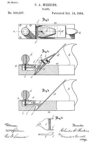
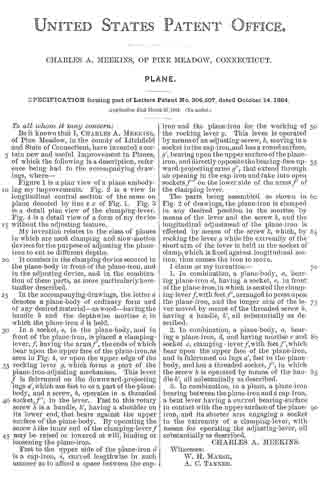
Figure 1 is a plan view of a plane embodying my improvements. Fig. 2 is a view in longitudinal central section of the same on plane denoted by line x x of Fig. 1. Fig. 3 is a detail plan view of the clamping-lever. Fig. 4 is a detail view of a form of my device without the adjusting feature.
My invention relates to the class of planes in which are used clamping and slow-motion devices for the purpose of adjusting the plane iron to cut to diiferent depths.
It consists in the clamping device secured in the plane-body in front of the plane-iron, and in the adjusting device, and in the combination of these parts, as more particularly hereinafter described.
In the accompanying drawings, the letter a denotes a plane-body of ordinary form and of any desired material — as wood — having the handle b and the depthwise mortise c, in which the plane-iron d is held.
In a socket, e, in the plane-body, and in front of the plane-iron, is placed a clamping-lever, f, having the arms f’, the ends of which bear upon the upper face of the plane-iron,as seen in Fig. 4, or upon the upper edge of the rocking lever g. which forms a part of the plane-iron-adjusting mechanism. This lever f is fulcrumed on the downward-projecting lugs a’, which are fast to or a part of the plane-body, and a screw, h, operates in a threaded socket, f”, in the lever. Fast to this rotary screw h is a handle, h’, having a shoulder on its lower end, that bears against the upper surface of the plane-body. By operating the screw h the inner end of the clamping-lever f may be raied or lowered at will, binding or loosening the plane-iron.
Fast to the upper side of the plane-iron d is a cap-iron, i, curved lengthwise in such manner as to afford a space between the cap-iron and the plane-iron for the working of the rocking lever g. This lever is operated by means of an adjusting-screw, k, moving in a socket in the cap-iron, and has a round surface, g’, bearing upon the upper surface of the plane-iron, and directly opposite the bearing-face upward-projecting arms g”, that extend through an opening in the cap-iron and take into open sockets f”’ on the lower side of the arms f’ of the clamping-lever.
The parts being assenibled as shown in Fig. 2 of drawings, the plane-iron is clamped in any desired position in the mortise by means of the lever and the screw h, and the longitudinal adjustrnent of the plane-iron is effected by means of the screw k, which, by rocking the lever g while the extremity of the short arm of the lever is held in the socket of clamp,which is fixed against longitudinal motion, thus causes the iron to move.
I claim as my invention —
1. In combination, a plane-body, a, bearing plane-iron d, having a socket, e, in front of the plane-iron, in which is seated the clamping-lever f, with feet f’, arranged to press upon the plane-iron, and the longer arm of the lever moved by means of the threaded screw h, having a handle, h’, all substantially as described.
2. In combination, a plane-body, a, bearing a plane-iron, d, and having mortise c and socket e, clamping-lever f, with feet f’, which bear upon the upper face of the plane-iron, and is fulcrumed on lugs a’, fast to the plane-body, and has a threaded socket, f2, in which the screw h is operated by means of the handle h’, all substantially as described.
3. In combination, in a plane, a plane-iron bearing between the plane-iron and a cap-iron, a bent lever having a curved bearing-surface in contact with the upper surface of the plane-iron, and its shorter arm engaging a socket in the extremity of a clamping-lever, with means for operating the adjusting-lever, all substantially as described.
CHARLES A. MEEKINS.
Witnesses:
W. H. MARSH,
A. C. TANNER.