
| PLEASE NOTE: The images presented on this page are of low resolution and, as a result, will not print out very well. If you wish to have higher resolution files then you may purchase them for only $2.95 per patent by using the "Buy Now" button below. All purchases are via PayPal. These files have all been cleaned up and digitally enhanced and are therefore suitable for printing, publication or framing. Each zip package contains all the images below (some packages may contain more), and purchased files can be downloaded immediately. |
UNITED STATES PATENT OFFICE.
_________________
JUSTUS A. TRAUT, OF NEW BRITAIN, CONNECTICUT.
BENCH-PLANE.
_________________
SPECIFICATION forming part of Letters Patent No. 306,877, dated October 21, 1884.
Application filed June 11, 1884. (No model.)
_________________
To all whom it may concern:
Be it known that I, JUSTUS A. TRAUT, a citizen of the United States, residing at New Britain, in the county of Hartford and State of Connecticut, have invented a new and useful Improvement in Bench-Planes, of which the following is a specification.
My invention relates to improvements in bench-planes, and the object. of my invention is to produce a better mechanism for adjusting the cutting-edge of the bit to square it with the stock. I attain this object by the simple construction illustrated in the accompanying drawings. in which —
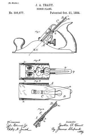
Figure 1 is a side elevation of my improved bench-plane. Fig. 2 is a sectional view thereof, partly in elevation, on line x x of Fig. 1. Fig. 3 is a like view with cutter attached, and Fig. 4 is a sectional view thereof on line y y of Fig. 2.
It is oftentimes difficult to grind the cutting-edge of a plane-bit exactly square, and therefore when set in place it does not stand square with the stock. Several prior patents show planes having mechanism for effecting this lateral adjustment of the cutting-bit edgewise. one of which mechanisms is a lever arranged under the bit at the upper end of the frog. Another consists of two screws the heads of which act upon the edges of the bit at the upper end of the frog. Another patent shows side screws near the middle of the stock, which, in connection with swinging dogs and a sliding piece, hold the bit in its adjusted position. All of said prior art is hereby disclaimed. The major portion of my plane is the same as ordinary bench-planes. The particular plane iilustrated is the one known as “Bailey’s patent plane.”
I secure the edgewise-adjusting lever a to the plane seat or frog by means of the rivet b and washer d, said washer producing sufficient friction to keep the lever a in place when the cap is removed. This lever is also let into the frog or bit seat A, so as to bring its upper side just below the under side of the bit. B, as shown in Figs. 1 and 4, and said frog or seat is also cut away, as at e, Fig. 2, in order to permit a lateral movement of the lever a. The lower end of said lever is provided with a projection, f, which rises above the surface of the frog or seat A a distance about equal to the thickness of the bit B, but not far enough to bind against the under surface of the cap-iron C. This projection f of a width which will about fill the ordinary slot for the cap-screw at the upper end of the bit. I prefer to provide the under side of the lever a with a small boss or trunnion concentric with the rivet b, on which it is fulcrumed, and sink said trunnion into a circular recess, as shown in Fig. 4; but this construction is not essential. I also provide the stock with stationary pins h h near the lower end of the bit B. upon which said bit can swing or fulcrum when moved edgewise. These pins are threaded merely for convenience of insertion; but when once inserted plain pins will answer the same purpose.
When the parts are in place ready for use, in order to adjust the bit edgewise to bring its edge square with the stock, it is only necessary to move the lever a to one side, as shown in Fig. 3, which illustrates a bit whose end is ground out of square to an unusual degree. It should be observed that the lever a is close up under the bit, and does not so project as to ever render any inconvenience whatever in the ordinary uses of the plane. I have shown this lever as the best-known mechanism for an edgewise adjustment of the bit; but other mechanism for this adjustment located at the upper end instead of the lower end of the stock will secure the advantages of my invention.
The stationary pins are located in the stock, so as to bear directly upon the edges of the bit near its cutting end, and, as the laterally-adjusting mechanism is operated to move the upper end of the bit edgewise, it will rock or fulcrum upon the stationary pins at the lower end.
My rnechanism for this edgewise adjustment does not in the least interfere with the ordinary endwise adjustment of the bit, and requires no change whatever in the ordinary parts of the plane, except to recess and drill the frog or bit and the stock for the reception and attachment of the lever a and pins h h.
I claim as my invention —
The combination of a plane stock and bit, an edgewise-adjusting mechanism for acting upon the bit at its upper end, and the stationary fulcrum-pins h h in the stock near the cutting end of the bit, substantially as described, and for the purpose specified.
JUSTUS A. TRAUT.
Witnesses:
JAMES SHEPARD,
EDDY N. SMITH.