
| PLEASE NOTE: The images presented on this page are of low resolution and, as a result, will not print out very well. If you wish to have higher resolution files then you may purchase them for only $2.95 per patent by using the "Buy Now" button below. All purchases are via PayPal. These files have all been cleaned up and digitally enhanced and are therefore suitable for printing, publication or framing. Each zip package contains all the images below (some packages may contain more), and purchased files can be downloaded immediately. |

UNITED STATES PATENT OFFICE.
_________________
JUSTUS A. TRAUT, OF NEW BRITAIN, CONNECTICUT, ASSIGNOR TO
THE STANLEY RULE AND LEVEL COMPANY, OF SAME PLACE.
RABBET-PLANE.
_________________
SPECIFICATION forming part of Letters Patent No. 308,332, dated November 18, 1884.
Application filed May 17, 1884. (No model.)
_________________
To all whom it may concern:
Be it known that I, JUSTUS A. TRAUT, a citizen of the United States, residing at New Britain, in the county of Hartford and State of Connecticut, have invented certain new and useful Improvements in Rabbet-Planes, of which the following is a specification.
My invention relates to improvements in rabbet-planes, and has for its object a better arrangement for the gages.
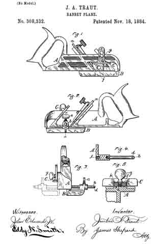
In the accompanying drawings, Figure 1 is a side elevation of my rabbet-plane. Fig. 2 is a like view of the reverse side of the same. Fig. 3 is an end view of the same. Fig. 4 is a sectional view of a portion of the stock on line x x of Fig. 2, said view also showing the gage-rod in side elevation 5 and Fig. 5 is a horizontal section of the depth-gage and a portion of the stock with a side elevation of the clamping-screw.
The stock A may be of any ordinary form; but as shown it is provided with two bit-seats, into either of which the cutting bit a may be secured. This feature of the stock, however, was known prior to my present invention. The bit a at the cutting end is the full width of the stock.
b is the gage-rod, upon which the socket of the gage B is fitted, so that the gage may be adjusted longitudinally upon said rod and fastened in place by means of the set-screw c, thereby securing the working-face of the gage B at any desired point with reference to the under surface of the stock. As shown in the drawings, this gage is adjusted for use in working from the left-hand edge of a board. The gage-rod b is secured to the stock by means of its threaded end and a correspondingly-threaded hole in the side of the stock. In order to facilitate the screwing out and in of this rod, I provide its end with an orifice into which a suitable pin or wrench may be applied. Upon the opposite side of the stock, and in alignment with the hole into which the gage-rod is secured, I form a like threaded hole, f, Figs. 1 and 4.
When it is desired to convert the tool to one for gaging from the right-hand edge of a board, the gage-rod b is unscrewed from one side of the stock, and then inserted in hole f, and the gage B then secured thereon, as indicated by broken lines in Fig. 3. By making the gage-rod attachable and detachable to and from either side of the stock the rods never project upon that side which is opposite the gage B, thereby enabling the gage and plane to be used in corners and cramped places where it is impossible to use a rabbet plane and gage whose gage-rods project upon said side.
C designates the depth-gage, the shank of which is slotted for insertion of the clamping-screw g, which passes through the shank of the depth-gage and into a threaded hole in the stock. The side of the stock to which this gage is secured is provided with a vertical V-shaped groove, h, Figs. 1 and 5, which groove is a little to one side of the clamping-screw g. The inner face of the gage C is provided upon one side of the clamping-screw with a V-shaped rib, k, and upon the opposite side of the screw is a plain-faced rib, l, Fig. 5. The V-shaped rib governs the position of the gage in its movement up and down, while the plane-faced rib, in connection with the V-shaped rib, forms a seat or bearing-surface to hold the gage at a proper distance from the side of the stock. This construction enables the gage to be governed in its vertical position, and to form a proper bearing-surface, only a small portion of which requires to be fitted, and consequently it can be fitted with but little labor and expense.
Any suitable spur or spurs may be attached to the side or sides of the stock just forward of the cutting-bit, as in prior rabbet-planes.
I am aware that depth-gages of various kinds have been heretofore employed upon rabbet-planes having side gages; also, that prior patents show rabbet-planes having side gages with two rods permanently secured thereto, and having transverse holes through the stock into which said gage-rods were inserted and held therein by means of set-screws, whereby the gage could be changed end for end, and placed upon either side of the stock to convert the tool into a right or left hand plane, as required. All of said prior art is hereby disclaimed.
I claim as my invention —
1. The herein-described rabbet-plane, consisting of the stock A, having screw-holes f upon opposite sides and in alignment with each other, the gage-rod b, screw-threaded upon its end to fit both of said holes in the stock, and the reversible gage B, having the set-screw c, and a socket for securing the rod b, all substantially as described, and for the purpose specified.
2. In a rabbet-plane, the combination of the stock A, having the groove h, the depth-gage C, having a central slot with the rib k fitted to rest upon the bottom of the groove h at one side of said slot, and the plane-faced rib l, which abuts against a plane surface on the stock at the opposite ends of said slot, the clamping-screw g, the gage-rod b, and the side gage, B, all substantially as described, and for the purpose specified.
JUSTUS A. TRAUT.
Witnesses:
H. S. WALTER,
HENRY C. HINE.