| PLEASE NOTE: The images presented on this page are of low resolution and, as a result, will not print out very well. If you wish to have higher resolution files then you may purchase them for only $2.95 per patent by using the "Buy Now" button below. All purchases are via PayPal. These files have all been cleaned up and digitally enhanced and are therefore suitable for printing, publication or framing. Each zip package contains all the images below (some packages may contain more), and purchased files can be downloaded immediately. |
UNITED STATES PATENT OFFICE.
_________________
EDWARD L. GAYLORD, OF BRIDGEPORT, CONNECTICUT.
PLANE FOR PICTURE-MOLDINGS.
_________________
SPECIFICATION forming part of Letters Patent No. 313,195, dated March 3, 1885.
Application filed September 3, 1884. (No model.)
_________________
To all whom it may concern:
Be it known that I, EDWARD L. GAYLORD, a citizen of the United States, residing at Bridgeport, in the county of Fairfield and State of Connecticut, have invented certain new and useful Improvements in Planes for Picture-Moldings; and I do hereby declare the following to be a full, clear, and exact description of the invention, such as will enable others skilled in the art to which it appertains to make and use the same.
My invention relates to certain novel and useful improvements in planes for picture-moldings, and has for its object to provide a device of this description which will accommodate and plane stock of any thickness and give to it any desired contour; and with these ends in view my invention consists in the details of construction and combination of elements hereinafter fully and in detail explained, and then specifically designated by the claims.
In order that those skilled in the art to which my invention appertains may more fully understand its construction and operation, I will proceed to describe the same in detail, referring by letter to the accompanying drawings, forming a part of this specification, in which —
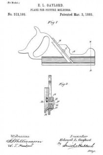
Figure 1 represents a side elevation of my improved plane; and Fig. 2, a vertical section of the plane at the line x x of Fig. 1, and showing the handle and iron in elevation.
Similar letters denote like parts in both figures of the drawings.
A is the stock, constructed as in ordinary planes of this description; and B is the iron, secured to its bed by bolt C, also as in ordinary planes. The sole J is conformed to the contour of the cut made by the iron.
D is the guide, which at its bearing-surface on the sole conforms to the latter in shape. It is provided with slots E, through which bolts F pass and secure it to the stock.
Between the sole of the plane and the surface of the guide which rests thereon is clamped a thin metal strip, H, which extends outward over the cutting-edge of the iron and prevents the latter from gouging or cutting the edge of the stock next the gage. The purpose of the strip H is to preserve the edge of the material intact and to make the iron cut up to that edge.
G are washers strung upon bolts F, and which are inserted or omitted, as the guide is required to extend less or more upon the surface of the sole. By inserting more washers stock of greater thickness may be accommodated, and by omitting them the plane will be adapted to thinner stock, while in both instances the shape of the planed surface will conform to the curvature of the cutting edge of the iron.
In my invention I do not wish to be understood as claiming, broadly, the application to a plane of a guide, for that I know to be old. The gist of my invention rests in the idea of applying to a molding-plane for frame-makers’ use a device whereby the capacity of the plane for thickness of stock may be diminished or increased, while at the same time the edge of the material and the curvature indicated by the contour of the plane-sole will be preserved in the finished surface.
Having thus described my invention what I claim as new, and desire to secure by Letters Patent, is —
1. The combination, with a plane of the character described, of a guide extending more or less over the plane-sole, and a metal strip extending along the cutting-edge of the iron next the gage, whereby stock of greater or less thickness may be accommodated and planed and the edge preserved intact, substantially as set forth.
2. The combination of stock A, iron B. slotted guide D, secured to the stock by bolts F, having washers G, and strip H, lying along the edge of the iron next the guide, all arranged as described, and for the purpose set forth.
In testimony whereof I affix my signature in presence of two witnesses.
EDWARD L. GAYLORD.
Witnesses:
S. S. WILLIAMSON,
W. T. HAVILAND.


