| PLEASE NOTE: The images presented on this page are of low resolution and, as a result, will not print out very well. If you wish to have higher resolution files then you may purchase them for only $2.95 per patent by using the "Buy Now" button below. All purchases are via PayPal. These files have all been cleaned up and digitally enhanced and are therefore suitable for printing, publication or framing. Each zip package contains all the images below (some packages may contain more), and purchased files can be downloaded immediately. |
UNITED STATES PATENT OFFICE.
_________________
WILLIAM TIDGEWELL, OF MIDDLETOWN, ASSIGNOR TO THE MERIDEN MALLEABLE IRON COMPANY, OF MERIDEN, CONNECTICUT.
JOINER’S PLANE.
_________________
SPECIFICATION forming part of Letters Patent No. 313,694, dated March 10, 1885.
Application filed February 2, 1885. (No model.)
_________________
To all whom it may concern:
Be it known that I, WILLIAM TIDGEWELL, of Middletown, in the county ot’ Midellesex and State of Connecticut, have invented a new Improvement in Joiners’ Planes; and I do hereby declare the following, when taken in connection with accompanying drawings and the letters of reference marked thereon, to be a full, clear, and exact description of the same, and which said drawings constitute part of this specification, and represent, in —
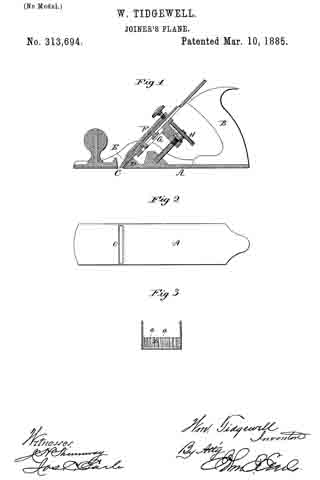
Figure 1, a longitudinal vertical section; Fig. 2, an underside view of the stock; Fig. 3, a transverse section through the stock, looking on the face ofthe bearing D.
This invention relates to an improvement in that class of joiners’ planes in which the stock is made from cast metal, and in which the cutter is made adjustable by mechanical appliances. In the usual construction of these planes the cutter takes a bearing upon the stock at the mouth, the bearing extending up a considerable distance on the back of the cutter.
This bearing-surface is usually smooth and the cutter fits close upon it. The result of this bearing is to create a very great friction between it and the cutter, owing to the pressure which is brought upon the cutter at the bearing in the clamping operation, so that when the cutter is so clamped a very considerable force is necessary to be applied to the adjusting device to move the cutter.
The object of my invention is to diminish this friction while still retaining practically the same extent of bearing; and it consists in grooving the face of the bearing so as to form a series of ribs upon which the cutter will rest, the bearing-surface being reduced to the extent of the area of the spaces between the ribs, as more fully hereinafter described.
A represents the stock, made from cast-iron, and provided with the usual handle, B. C is the mouth; D, the bearing directly in rear and above the month, upon which the lower portion of the cutter E rests; F, the clamp applied in the usual manner for binding the cutter upon its seat D; G, the movable bed to which the cutter is also clamped; H, the adjusting device applied to the bed or slide G, and by which said slide and cutter are moved to adjust the cutter.
The clamping device, bed, and adjusting device may be any of the known constructions.
The face of the bearing D, instead of being made flat, is corrugated, as seen in Fig. 3, so as to form a series of ribs, a a, more or less in number, these ribs forming a series of narrow bearings, upon which the cutter will rest and its proper position be insured, yet over which it will easily move under the action of the adjusting devices.
As here represented, the area of all the ribs amounts to about one-third of the area of the bearing. The friction therefore is reduced accordingly; but still the same firm support is given to the cutter. These grooves should terminate near the bottom surface of the stock, or at about where the bevel at the edge ofthe cutter begins, as seen in Figs. 1 and 3. These grooves may be formed in casting, the ribs subsequently dressed to finish the bearing for the cutter.
In the illustration I have shown a construction of plane which permits of but a short bearing for the lower end of the cutter; but in other well-known constructions the extent of bearing is very much greater, even to forming the entire support for the cutter. The advantages of my invention increase as the extent of the bearing increases.
I claim —
In a joiner’s plane in which the stock is of cast metal, and in which the cutter is made adjustable, the bearing, D in the rear of the mouth, and which supports the cutter, constructed to form a series of ribs upon its face, and upon which ribs the cutter will rest, substantially as described.
WILLIAM TIDGEWELL.
Witnesses:
GEO. W. SMITH,
ELI I. MERRIMAN.


