
| PLEASE NOTE: The images presented on this page are of low resolution and, as a result, will not print out very well. If you wish to have higher resolution files then you may purchase them for only $2.95 per patent by using the "Buy Now" button below. All purchases are via PayPal. These files have all been cleaned up and digitally enhanced and are therefore suitable for printing, publication or framing. Each zip package contains all the images below (some packages may contain more), and purchased files can be downloaded immediately. |

UNITED STATES PATENT OFFICE.
_________________
JAMES MANDER, OF PHILADELPHIA, PENNSYLVANIA,
ASSIGNOR OF ONE-THIRD TO MAURICE R. DILLIN, OF SAME PLACE.
CHAMFER-PLANE.
_________________
SPECIFICATION forming part of Letters Patent No. 314,338, dated March 24, 1885.
Application filed December 18, 1884. (No model.)
_________________
To all whom it may concern:
Be it known that I, JAMES MANDER, a subject of the Queen of Great Britain, residing at Philadelphia, in the county of Philadelphia and State of Pennsylvania, have invented certain new and useful Improvements in Chamfer-Planes, of which the following is a specification.
My invention relates to an improvement in planes to be used to chamfer the right-angled edge of a board or strip and form the beveled ends of the chamfer in the manner heretofore accomplished by hand with the chisel, drawing-knife, and level-faced bench-plane.
The invention consists of a bench-plane whose face or working-surface is rabbeted from nearly the edges of its sides to a point within and central with the body of the plane, the lines of the rabbet intersecting each other at an angle of ninety degrees, so that when the chamfered edge of the board is brought to the required depth, as may be regulated by the adjustable face, the sides of said rabbet rest equally and firmly upon the edge and face of the board. The main element of the invention, however, consists of an adjustable sliding face in connection with the rabbeted face of the plane, which is situated in front of the cutting-bit and its retaining-wedge. Said face is also wedged-shaped, and extends down from above the upper surface through the body of the plane and projects within the rabbeted surface any distance desired, and held firmly in position by set-screws that are adjustable in the opposing sides of the plane.
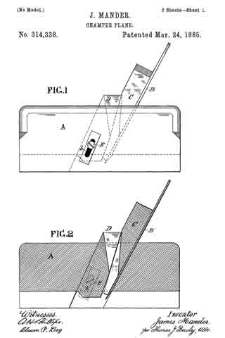
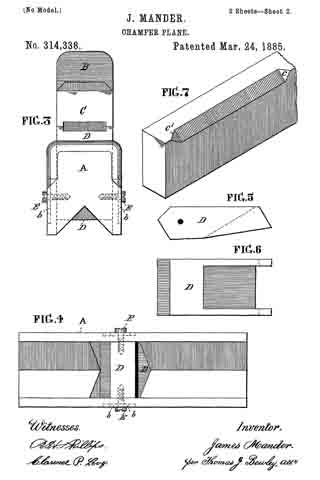
In the accompanying drawings, which make a part of this specification, Figure 1 is a side elevation of my improved plane. Fig. 2 is a longitudinal section of the same. Fig. 3 is an end view. Fig. 4 is a view of the working-face of the plane. Figs. 5 and 6 are side and face views of the adjustable sliding wedge-face D. Fig. 7 is an isometrical view of a portion of a strip chamfered on one corner.
Like letters of reference in all the figures indicate the same parts.
A is the plane-stock; B, the cutting-bit; C, the wedge which retains said bit in position. D is the adjustable sliding face, situated in front of the wedge C and extending from the upper surface down through the body of the plane. It is capable of being adjusted in its altitudinal position by means of the set-screws E E, the ends of which pass into it, the stems of said screws sliding in the slots b b in the sides of the stock.
The mode of operation is as follows: The bit B and its retaining-wedge C are placed in the stock A in the usual manner, the face D having been previously adjusted, with its lower end extending down into the angled rabbeted sides of the stock the required distance below which it is desired to cut the chamfer. The plane is then manipulated in the customary manner, with one side of the angled face upon the edge and the other upon the surface of the board, nearly the required length of the charnfer, cutting the end bevel, c, during its progress, when it is reversed and worked (left-handed) to cut the other end bevel, c’, and the remaining portion of the chamfer down to its level. The working-surface of the adjustable face D extends back only to the front of the cutting-edge of the bit B, with sufficient room between it and the bit for the upward passage of the shaving to the throat of the plane. The face of the stock being rabbeted its entire length presents no obstacle to the bit acting as a chisel or similar tool, thereby cutting the beveled end of the chamfer.
In lieu of a flat chamfer, the corner of the board may be beaded, reeded, fluted, or given any desired configuration by a corresponding change in the face of the adjustable stop and in the cutting-edge of the bit.
Having thus described the construction and operation of my improved plane, what I claim therein as new, and desire to secure by Letters Patent, is —
1. The adjustable face D, in combination with the rabbeted faced stock A, said face D being cofined within the body of the stock A by means of the set-screws E E, which pass through the sides of the stock to engage the face D, whereby said face D may be raised or lowered to suit the depth of chamfer required, substantially as described.
2. The stock A, which forms the stop or depth of chamfer, rabbeted throughout its length from a central point at an angle of ninety degrees each way to its sides, in combination with the adjustable face D, which is secured in the stock and made adjustable therein by means of the screws E E and cutting-bit B, thus leaving the back of the bit free to act as a chisel for cutting the beveled end of the chamfer.
JAMES MANDER.
Witnesses:
THOMAS J. BEWLEY,
FRANK CRAVEN.