
| PLEASE NOTE: The images presented on this page are of low resolution and, as a result, will not print out very well. If you wish to have higher resolution files then you may purchase them for only $2.95 per patent by using the "Buy Now" button below. All purchases are via PayPal. These files have all been cleaned up and digitally enhanced and are therefore suitable for printing, publication or framing. Each zip package contains all the images below (some packages may contain more), and purchased files can be downloaded immediately. |
UNITED STATES PATENT OFFICE.
_________________
JUSTUS A. TRAUT, OF NEW BRITAIN, CONNECTICUT, ASSIGNOR TO
THE STANLEY RULE AND LEVEL COMPANY, OF SAME PLACE.
PLANE.
_________________
SPECIFICATION forming part of Letters Patent No. 316,079, dated April 21, 1885.
Application filed February 25, 1885. (No model.)
_________________
To all whom it may concern:
Be it known that I, JUSTUS A. TRAUT, a citizen of the United States, residing at New Britain, in the county of Hartford and State of Connecticut, have invented certain new and useful Improvements in Planes, of which the following is a specification.
My plane is principally designed for use in making chamfer moldings on the corners of pieces of wood-work for various uses.
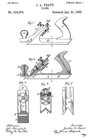
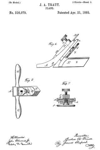
In the accompanying drawings, Figure 1 is a side elevation of my plane. Fig. 2 is a central longitudinal section thereof. Fig. 3 is a transverse section thereof on line x x of Figs. 1 and 2. Fig. 4 is a view of the stock proper, or the front part of my plane as seen when looking squarely upon the rear under side of its oblique face. Fig. 5 is a corresponding view of the rear part, showing the upper side of its oblique face. Fig. 6 is a side elevation, partly in section, of one of my planes, having a shorter rear part on gage and with the handles omitted. Fig. 7 is a transverse section of a part of the same on line y y of Fig. 6, but partly in elevation; and Fig. 8 is a plan view of one of my planes with a different form of handle.
A designates the stock proper, having the usual oblique frog, in which the ordinary cutter B is seated. This cutter is held in place by the holding-cap C, all as in ordinary planes. Other ordinary means of holding the cutter, either with or without special mechanism for adjusting the cutter up and down, may be substituted for that shown. The rear end of the stock proper, A, is an oblique under face, upon which I form a central and longitudinal rib, a, having straight, smooth edges. The front end of the stock proper, A, may, if desired, be provided with the knob-shaped handle D, with the exception of the ribbed oblique under face at the rear. The parts so far described are nothing more than an ordinary plane, and they are capable of use as such without the addition of other parts.
E designates a gage having an angular groove, b, extending longitudinally through its under face. Its front end is provided with an oblique flange or frog, c, slotted at its upper end, and provided with a groove, d, into which the rib at of the stock proper fits, so that the two parts are guided one upon the other. A shouldered set-screw, f passes through the slotted upper end of the flange or frog c, and into the oblique portion of the stock proper, A. By tightening this screw the parts A and E are held firmly in their adjusted position. By loosening the screw said parts may be moved one upon the other to any desired position and held there by tightening the screw again.
Inasmuch as the chamfer made by my plane is generally made to stop short of the length of the piece charnfered, I bevel off the lower rear corner of the stock proper, A, as at g, to a bevel corresponding to the bevel of the cutter at its lower end. This enables me to cut a beveled or oblique shoulder at the end of the chamfer cut by my plane, the angle of which shoulder will be the same as that of the beveled-off portion g of the stock.
For chamfering a corner, the parts A and E are adjusted so that the flat under face at the front end of the stock proper extends below the apex of the groove b just the depth of the desired chamfer. The plane is moved back and forth, with its gage E set squarely, as is practicable, over the corner to be chamfered, and shaving after shaving removed, until the gage stops further cutting by resting firmly for its whole length upon the stock being chamfered.
By inserting different forms of cutters moldings of different forms may be chamfered off or formed on the corners of wood-work, but the straight cutter for a plain chamfer will be the most generally used. The gage E may, if desired, be provided with the handle F. I make the rear end of the gage slanting, as shown, in order that it may be the better seated upon the work in starting a chamfer. By placing the stock proper upon the extreme front end of the gage E, I can make them of the same width, so that when adjusted to bring their lower faces into the same plane the device may be used as an ordinary hand-plane for planing flat surfaces.
Instead of handling the tool as an ordinary plane for chamfering, it may be handled after the manner of a spokeshave by simply providing the stock proper, A’, Fig. 8, with side handles, G G, as shown in said figure, or like handles may be formed in like manner upon the sides of the gage E, near its front end.
I am aware that planes for chamfering have heretofore been made, and I do not claim the same, broadly. Neither do I wish to limit my invention to the specific means of fastening the parts A and E in their adjusted positions, as other ordinary mechanism may be substituted therefor.
I claim as my invention —
The combination of the gage E, having the longitudinal angular groove b, with the stock proper, A, adjustable up and down upon the oblique front end of said gage, substantially as described, and for the purpose specified.
JUSTUS A. TRAUT.
Witnesses:
H. S. WALTER,
CHAS. B. STANLEY.