
| PLEASE NOTE: The images presented on this page are of low resolution and, as a result, will not print out very well. If you wish to have higher resolution files then you may purchase them for only $2.95 per patent by using the "Buy Now" button below. All purchases are via PayPal. These files have all been cleaned up and digitally enhanced and are therefore suitable for printing, publication or framing. Each zip package contains all the images below (some packages may contain more), and purchased files can be downloaded immediately. |

UNITED STATES PATENT OFFICE.
_________________
JOHN P. GAGE , OF VINELAND, NEW JERSEY.
BENCH-PLANE.
_________________
SPECIFICATION forming part of Letters Patent No. 323,804, dated August 4, 1885.
Application filed April 23, 1885. (Model.)
_________________
To all whom it may concern:
Be it known that I, JOHN P. GAGE, a citizen ofthe United States, residing at Vineland, in the county of Cumberland and State of New Jersey, have invented certain new and useful Improvements in Bench-Planes; and I do declare the following to be a full, clear, and exact description of the invention, such as will enable others skilled in the art to which it appertains to make and use the same, reference being had to the accompanying drawings, and to letters or figures of reference marked thereon which form a part of this specification.
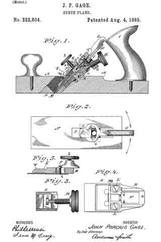
Figure 1 of the drawings is a representation of a longitudinal section of my invention. Fig. 2 is a view of the cutter and the pivoted finger-lever removed from the plane. Fig. 3 is a view of the adjusting-screw and cutter-bearing removed. Fig. 4 is a detached view of the bearing-plate, and Fig. 5 is a sectional view of the fellow plate and cup-plate with the bearing-screw and casting applied.
This invention has relation to improvements in carpenters’ planes; and it consists in certain novel devices, as hereinafter set forth, and pointed out in the appended claims.
In the accompanying drawings, the letter A designates the body of the plane, which is formed with an oblique transverse slot, B, for the cutter and its. adjusting devices. C is the handle.
D is a metal bearing, which is set into the oblique slot B, and is secured therein. The lower face of this bearing is flush with the bearing-face of the plane-body, and may be made a little concave in its middle portions, or between its front and rear bearing-edges. This metal bearing is provided with an extension, E, backward and upward, which is slotted at F, and has a threaded bearing at G for the adjusting-screw H. It is also provided with lateral stops K.
L L are the elongated openings or slots through which the fastening-screws pass. A transverse bearing, m, is provided, usually in rounded or rod form, which is located upward and forward from the main face of the casting, on which the cutter rests.
N is the cutter, slotted at P, and provided with an under bearing, R, which is designed to engage the enlarged end a of the adjusting-screw. This bearing descends into the opening B of the casting D when the cutter is applied in position.
S is a lever having its fulcrum-bearing c in the slot of the cutter, and engaging a stud, d, of the bearing B, or of its fellow plate T, which is firmly secured to said bearing B, usually by a screw, e. The handle of the lever S projects backward and upward within easy reach of the fingers. The object of this lever movement is to enable the operator to adjust the cutter laterally, so that when its cutting-edge is inclined or out of trim a single movement of the lever to the right or left, as the case may require, will correct the deviation and bring the cutting-edge into true relation with the bearing-face of the plane. Other forms of lever-connections may be employed with the cutter, or the adjustment may be made by means of lateral screws, or a screw may be employed, extending downward and forward, to operate an eccentric in connection with the cutter. Many devices to effect this lateral adjustment of the cutter-plate will occur to those skilled in the art.
V is the cap-plate, which is adjustable by means of screws g g passing through siots h h, in the fastening-piece or top casting, V, which carries the bearing-screw Z. This top V is formed with a concave rounded bearing, k, adapted to engage the transverse rod an and hold the fastening-piece or cap-plate firmly in position.
Having described this invention, what I claim, and desire to secure by Letters Patent, is —
1. In a plane, the combination of the slotted cutter, the under bearing, B, having a stud, d, and operated by means of the adjusting-screw, the fellow plate, screw connecting the fellow plate and bearing R, lever S, and its fulcrum-bearing c, arranged in the slot of the cutter, substantially as specified.
2. The combination of the slotted cutter, a bearing arranged beneath the same, with a stud passing through the slot of the said cutter, a fellow plate connected with the said under bearing, the finger-lever, and its fulcrum-bearing, as c, arranged in the slot, wherby lateral deviations of the cutting-edge may be corrected, substantially as specified.
3. A plane having an lever adapted to correct deviations in the edge of the cutter, which lever has its lower end pivoted in a longitudinal slot of the cutter, and provided with a stud to engage and move laterally a fulcrum-bearing in the said slot, substantially as specified.
In testimony whereof I affix my signature in presence of two witnesses.
JOHN P. GAGE.
Witnesses:
THEO. MUNGEN,
PHILIP C. MASI.