
| PLEASE NOTE: The images presented on this page are of low resolution and, as a result, will not print out very well. If you wish to have higher resolution files then you may purchase them for only $2.95 per patent by using the "Buy Now" button below. All purchases are via PayPal. These files have all been cleaned up and digitally enhanced and are therefore suitable for printing, publication or framing. Each zip package contains all the images below (some packages may contain more), and purchased files can be downloaded immediately. |
UNITED STATES PATENT OFFICE.
_________________
JUSTUS A. TRAUT, OF NEW BRITAIN, CONNECTICUT, ASSIGNOR TO
THE STANLEY RULE AND LEVEL COMPANY, OF SAME PLACE.
BEADING-TO0L.
_________________
SPECIFICATION forming part of Letters Patent No. 335,856, dated February 9, 1886.
Application filed September 24, 1885. Serial No. 179,027. (No model.)
_________________
To all whom it may concern:
Be it known that I, JUSTUS A. TRAUT, a citizen ofthe United States, residing at New Britain, in the county of Hartford and State of Connecticut, have invented certain new and useful Improvements in Beading-Tools, of which the following is a specification.
My invention relates to improvements in hand beading-tools of the class which are similar to “spokeshaves;” and the objects of my invention are to simplify the construction of the tool, and at the same time to make it convenient and efiicient in use.
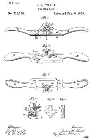
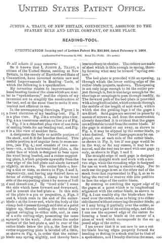
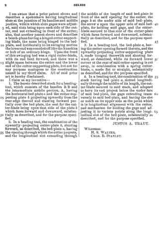
In the accompanying drawings, Figure 1 is a front elevation of my beading-tool. Fig. 2 is a plan view. Fig. 3 is a reverse plan view. Fig. 4 is a transverse section on line x x of Fig. 1. Fig. 5 is a detached plan view of one form of cutting-blade for my beading-tool, and Fig. 6 is a like view of another form.
A designates the body or middle portion of the stock, and B B the handles thereof. This middle portion is of angular form in cross-section, (see Fig. 4) and consists of two members — viz., a thin horizontal bed-plate, a, the under face of which is designed to bear upon the wood being beaded, and a cutter-supporting plate, b, which projects upwardly from the rear edge of the bed-plate and slants forward slightly, as shovvn. The cutter-blade c, having a slot or slots, as shown in Figs. 6 and 5, respectively, and having any desired form or forms of cutting-edge, I clamp to the front side of the supporting-plate b by means of bolt d and thumb-nut f. By “front side” I mean the side which faces forward and downward, and is nearest the bed-plate a. In this side of the plate is a pin or projection, g, Figs. 3 and 4, which rests in the slot of the cutter-blade c at the lower end, while the body of the clamp-bolt d passes through said slot at a point higher up, thereby holding the cutter firmly against swinging to either side, and, in case of a wide cutting-edge, presenting the same squarely to the work. Just above the under surface of the bed-plate a, and in rear of the cutter-blade below the pin g, the face of the cutter-supporting plate is beveled off a little, as shown in Fig. 4, in order that the cutter-blade may spring slightly, and thereby have less tendency to chatter. The cutters are made of steel which is thin enough to spring, thereby forming what may be termed “spring-cutters.”
The bed-plate is provided with an opening, through which the lower cutting-edge of the cutter-blade projects, as shown. This opening is not only large enough to let the cutter project through it, but is also large enough for the shavings or scrapings to pass through readily. The forward part of the bed-plate is provided with a longitudinal slot, which extends through the middle of the length of said stock, within which slot the guiding-lugs h of the gages k are fitted. Said gages are secured in place by rneans of screws n, and from the construction already described it is evident that the gages are adjustable to and from the cutter-blade. If the gage is slotted or cut away, as shown in Fig. 4, it may be slipped by the cutter-blade, when desired. Two of these gages may be employed, one at each side ot the cutter-blade, as shown in Fig. 3; but if one gage would be in the way, or for any reason, it may be removed, and the tool can be used with one gage only, as shown in Figs. 1 and 2.
The straight-edge of each gage is designed for use on straight work and work with a convex edge, while the rounding edge is designed for use on work having a concave edge. For such use the gage is set at the other end of the stock from that represented in Fig. 3, so as to bring the curved or convex side into position to face the edge of the cutter-blade.
By slotting or notching the upper edge of the gages at a point which is in longitudinal alignment with the cutter-blade, as shown in Fig. 4, I can readily slip the blade when loosened over the cutter, so as to bring it to either side thereof without removing the cutter- blade; or I may bring it partially over the cutter, so as to cover a part of its cutting-edge, and then I can use the exposed edge of the cutter for forming a bead or beads at the corner of a piece of work which corresponds to the exposed edge of the cutter.
I am aware that it is not new to use a cutter-blade having edges properly formed for beading or fluting in a stock similar to that of a spokeshave, and I hereby disclaim the same.
I am aware that a prior patent shows and describes a spokeshave having longitudinal slots at the junction of its handles and middle portion, within which slots gages were adjusted, said slots being upon each side of the cutter, and not extending in front of the cutter; also, that another patent shows and describes a bench-plane having a hinged cutter-supporting blade, the same being hinged to the bed-plate, and incidentally to its swinging motion the lower end was rounded off like the knuckles or hub of an ordinary hinge. Upon the front of this swinging bed was a rigid cutter-blade, with its end bent forward, and there was a slight space between the cutter and the lower end of the cutter-supporting plate, but not for any purpose analogous to the construction named in my third claim. All of said prior art is hereby disclaimed.
I claim as my invention —
1. The herein-described stock for a beading-tool, which consists of the handles B B and the intermediate middle portion, A, having the horizontal bed-plate a and the cutter-supporting plate b projecting upwardly from the rear edge thereof and slanting forward partially over the bed-plate, the seat for the cutter-blade being upon that side of the plate b which faces forward and downward, substantially as described, and for the purpose specified.
2. In a beading-tool, the combination of the upwardly-projecting cutter-plate b, slanting forward, as described, the bed-plate a, having the opening through which the cutter projects, and the longitudinal slot extending through the middle of the length of said bed-plate in front of the said opening for the cutter, the gage k at the under side of said bed-plate, the screw n upon the upper side of said bed-plate, for holding said gage, and the cutter-blade secured to that side of the cutter-plate which faces forward and downward, substantially as described, and for the purpose specified.
3. In a beading-tool, the bed-plate a, having the cutter-opening formed therein, and the upwardly-projecting cutter-supporting plate b, made integral therewith and slanting forward, as described, while its forward lower corner at the rear of said cutter-opening is cut away, in combination with a spring cutter-blade, c, made flat or straight, substantially as described, and for the purpose specified.
4. In a beading-tool, the combination of the stock having bed-plate a, slotted longitudinally through the middle of its length, the cutter-blade secured to said stock, and adapted to have its end project below the under face of said bed-plate, the gage extending transversely to said bed-plate, and having the slot or notch on its upper side at the point which is in longitudinal alignment with the cutter, and mechanism for holding the gage and adjusting it to various points along the longitudinal slot of the bed-plate, substantially as described, and for the purpose specified.
JUSTUS A. TRAUT.
Witnesses:
H. S. WALTER,
CHAS. B. STANLEY.