
| PLEASE NOTE: The images presented on this page are of low resolution and, as a result, will not print out very well. If you wish to have higher resolution files then you may purchase them for only $2.95 per patent by using the "Buy Now" button below. All purchases are via PayPal. These files have all been cleaned up and digitally enhanced and are therefore suitable for printing, publication or framing. Each zip package contains all the images below (some packages may contain more), and purchased files can be downloaded immediately. |

UNITED STATES PATENT OFFICE.
_________________
JAMES H. FERGUSON, OF BROOKLYN, ASSIGNOR TO
LOVEJOY, SON & Co., OF NEW YORK, N. Y.
EDGE-GUARD FOR PLANES.
_________________
SPECIFICATION forming part of Letters Patent No. 336,222, dated February 16, 1886.
Application filed October 3, 1885. Serial No. 178,870. (No model.)
_________________
To all whom it may concern:
Be it known that I, JAMES H. FERGUSON, of the city of Brooklyn, in the county of Kings and State of New York, have invented a new and Improved Edge-Guard for Planes, of which the following is a specification.
My invention is applicable both to planes in which the plane iron or knife is fixed in a stationary frame and performs its work when a piece of material is pushed over it, and to planes in which the iron or knife is fixed in a plane body or stock which is moved by hand over the work.
The object of my invention is to protect and shield or guard the knife so that it cannot receive injury by striking against any metal which would dull or chip its edge, and so that the hands of a workmen on a machine which comprises a plane iron or knife set in a stationary frame cannot be injured by coming in contact with the iron or knife.
To this end my invention consists in the combination, with the body and knife of a plane, of an edge-guard forming the edge of
the throat in front of the cutting-edge, and a spring for projecting the guard from the body so that it will shield the cutting-edge. This guard may be hinged at its side which is most distant from the cutting-edge of the plane-iron, and this arrangement therefore also forms a part of my invention.
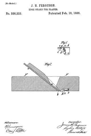
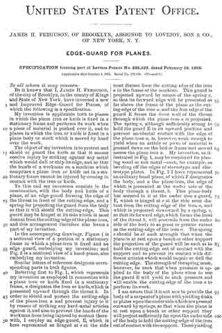
In the accompanying drawings, Figure 1 is a sectional view of a portion of a stationary frame in which a plane-iron is fixed and an edge-guard, embodying my invention; and Fig. 2 is a sectional view of a hand-plane, also embodying my invention.
Similar letters of reference designate corresponding parts in both figures.
Referring first to Fig. 1, which represents my invention as employed in connection with a plane iron or knife fixed in a stationary frame, a designates the iron or knife, which is presented upward through the throat b. In order to shield and protect the cutting-edge of the plane-iron a and prevent injury to it by reason of striking any hard-metal articles against it, and also to prevent the hands of the workmen from being injured by contact therewith, I employ an edge-guard, E, which is here represented as hinged at e at the side most distant from the cutting-edge of the iron a in the frame of the machine. This guard is projected upward by means of the spring c, so that its forward edge will be presented as far above the frame of the plane as the cutting-edge of the iron a, and the free edge of the guard E forms the front wall of the throat through which the plane-iron a is projected. The spring c, although sufficiently strong to hold the guard E in its upward position and prevent accidental contact with the edge of the plane-iron a, is, however, weak enough to yield when an article or piece of material is pressed down on the bed or frame and moved across the plane-iron a. My invention. as illustrated in Fig. 1, may be employed for planing wood or soft metal — such, for example, as beveling off the edges of stereotype and electrotype plates. In Fig. 2 I have represented an ordinary hand-plane, of which F designates the body, and a the plane-iron, the edge of which is presented at the under side of the body through a throat, b. This plane-body has secured in it at the under side a guard, E, which is hinged at e at the side most distant from the cutting edge of the iron a, and which is projected downward by a spring, c, so that its forward edge, which forms the front of the throat b, will protrude from the under side of the body to as great or greater extent as the cutting-edge of the iron a. The spring c should be of such strength that when the plane is at rest upon a bench or other support the projection of the guard will be such as to hold the cutting-edge out of contact with the support and to prevent its contact with different articles which would impair or dull the cutting-edge. The strength of the spring must, however, be such that when pressure is applied to the body of the plane when in use the guard E will yield to such pressure and will enable the cutting-edge of the iron a to perform its work.
I am aware that it is not new to provide the body of a carpenter’s plane with yielding disks or plates upon the under side which are pressed outward by springs, so that when the plane is at rest upon a bench or other support they will project sufficiently far upon the under side of the body to hold the cutting-edge of the iron out of contact with the support. These yielding disks or plates are, however, remote from the throat of the plane, and do not perform the function of my edge-guard E in protecting the edge of the cutting iron or knife, as they do not form the edge of the throat in front of the cutting-edge.
What I claim as my invention, and desire to secure by Letters Patent, is —
1. The combination, with the body and knife of a plane, of an edge-guard forming the edge of the throat of the cutting-edge, and a spring for projecting the guard from the body so that it will shield the cutting-edge, substantially as herein described.
2. The combination, with the body and knife of a plane, of an edge-guard forming the edge of the throat in front of the cutting-edge and hinged at its side which is most distant from the cutting-edge, and a spring for projecting the guard from the body so that it will shield the cutting-edge, substantially as herein described.
JAMES H. FERGUSON.
Witnesses:
FREDK. HAYNES,
HENRY McBRIDE.
Correction in Letters Patent No. 336,222.
It is hereby certified that in Letters Patent No. 336,222, granted February 16, 1886, upon the application of James H. Ferguson, of Brooklyn, N. Y., for an improvement in “Edge-Guards for Planes,” certain words were erroneously omitted in printing the specification, which should be supplied, to wit: In line 11, page 2, after the word “throat” the words in front should be inserted; and the Letters Patent should be read with this correction therein to conform to the record of the case in the Patent Office.
Signed, countersigned, and sealed this 23d day of February, A. D. 1886.
[SEAL.]H. L. MULDROW,
Acting Secretory of the Interior.
Countersigned:
M. V. MONTGOMERY,
Commissioner’ of Patents.