| PLEASE NOTE: The images presented on this page are of low resolution and, as a result, will not print out very well. If you wish to have higher resolution files then you may purchase them for only $2.95 per patent by using the "Buy Now" button below. All purchases are via PayPal. These files have all been cleaned up and digitally enhanced and are therefore suitable for printing, publication or framing. Each zip package contains all the images below (some packages may contain more), and purchased files can be downloaded immediately. |
UNITED STATES PATENT OFFICE.
_________________
JUSTUS A. TRAUT, OF NEW BRITAIN, CONNECTICUT, ASSIGNOR TO
THE STANLEY RULE AND LEVEL COMPANY, OF SAME PLACE.
BENCH-PLANE.
_________________
SPECIFICATION forming part of Letters Patent No. 338,570, dated March 23, 1886.
Application filed February 1, 1886. Serial No. 190,388. (No model.)
_________________
To all whom it may concern:
Be it known that I, JUSTUS A. TRAUT, a citizen of the United States, residing at New Britain, in the county of Hartford and State of Connecticut, have invented certain new and useful Improvements in Planes, of which the following is a specification.
My invention relates to improvements in planes for forming moldings at the corners and edges of various work; and the object of my invention is to improve the efficiency of such plane, especially when a bead or molding of any considerable depth is to be formed.
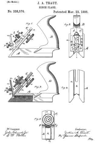
In the accompanying drawings, Figure 1 is a side elevation of my improved plane. Fig. 2 is a front view thereof. Fig. 3 is a vertical section, partly in elevation, of the front end of my plane, the plane of section being indicated by the line x x in Fig. 2. Fig. 4 is a detached view of the stock or guide as viewed in looking squarely upon the inclined face at its front end; and Fig. 5 is a detached view of the parts, which are fitted to said inclined face as viewed by looking squarely upon the inclined under face of said parts.
The main portion of my device is well adapted to be manufactured and sold as an attachment to accompany the plane patented to me April 21, 1885, No. 316,079. It may, however, be sold as a complete tool by itself. The stock or guide A has a V-shaped slot extending longitudinally through its under face, and I will therefore designate it as the “V-shaped guide.” The forward end of this guide is provided with an oblique flange or frog, a, slotted at its upper end and provided with a groove, b, Fig. 4, which extends length-wise through the middle of its front face. This V-shaped guide may be provided with the handle B, like an ordinary bench-plane, or it may be made without any special handle for use as a small block-plane, or it may be provided with side handles after the manner of a spokeshave, all as suggested and described in my aforesaid prior patent. This V-shaped guide is in fact the same as the part termed the “gage E” in said patent.
My present invention consists of the device or attachment which I have constructed for use in connection with this V- shaped guide.
C designates the holding-block, having up on its under side a central projection or rib, which, by being fitted to the groove b in the frog a, serves as a guide in seating and adjusting the holding-block in place upon the inclined front of said guide. This holding-block is provided with a flange, d, which serves as one of the nuts for the feeding-screw f. This holding-block is also provided with lugs g, which serve as guides for the cutter-block D. This cutter-block is provided upon its under side with a central rib, h, Fig. 5, which is also fitted to the groove b, andserves to guide the cutter-block within said groove. This cutter-block I provide with a flange, k, which serves as a nut for the other end of the feeding-screw f. The lower forward end of the cutter-block D is provided with the frog m, upon which the cutter n is mounted, and held in position thereon by any suitable fastening mechanism — as, for instance, by means of the yoke o and clamp-screw p. The frog in stands at such an angle to the cutter-block that when the block is mounted in place and the V-shaped guide is in a horizontal position the upper end of the cutter slants forward of a vertical line, so as to give the cutter a scraping action in forming beads or moldings. The nut or flange k is made thin and preferably beveled a little on both sides of its threaded hole, so that the cutter-block may rock a little, as on a pivot, when the plane is being drawn backward, and thereby relieve the cutter from injurious contact with the work. When the plane is moved forward, the cutter-block is seated firmly on the frog of the V-shaped guide, while its rear upper end is held-against said frog by means of the lug g.
The cutter-block C is held in position by means of a clamp-screw, r, the body of which extends through the slotted upper end of the flange or frog a.
Cutters for forming moldings or beads have been heretofore combined with a stock or V-shaped guide; but so far as I know they have been used by first setting the cutter-block and cutter so that the cutter will project the desired depth of cut into the face of the V-shaped groove in the stock or guide in the same manner as described in my former patent for setting the plane proper upon the front end of said guide. This is well enough for forming a chamfer, as the guide will properly bring the straight cutter into position when said guide comes to a bearing, the straight cutter being incapable of cutting beyond its proper depth, even if the V-shaped guide may be rocked a little out of square; but in cutting beads or deep moldings, if the plane is tipped a little to one side the corners may cut into the work so deeply in the beginning of the operation as not to have their marks obliterated when the guiding-surfaces come to a bearing. By my invention I avoid this contingency of marring the work.
My plane may be used for forming moldings directly upon the corner or upon a corner which has been previously chamfered, or upon the edge of any board or strip that may be received within the V-guide.
To use my plane upon the corner of any piece of work, I first turn the feed-screw back to bring the cutter-block and holding-block close together, as shown, then loosen the screw r, so that the holding-block C may be raised to the upper part of the frog a. I then place the V-shaped guide A firmly and squarely upon the corner of the piece to be operated upon and lower the holding-block until the cutter strikes the work. I then tighten the screw r to fasten the holding-block C in place, and push the plane over the surface to be molded, then draw it back again, meanwhile turning the feeding-screw a little to feed the cutter down the proper distance for the next cut, then push the plane over the work again, and, drawing it back, feed the cutter downward again, and so on until the molding is perfected, thereby keeping the V-shaped guide at all times squarely upon the work, so that, no matter what may be the shape of the cutter, it cannot produce a faulty cut. The feeding-screw f is a right-and-left-handed screw, and is well-known as a feeding mechanism. I have represented it as a convenient form of feeding mechanism for this purpose; but it is evident that other forms may be substituted therefor without avoiding my invention. It is also evident that my invention does not reside in the particular form of holding-block, inasmuch as I believe that a holding-block, cutter-block, and feeding mechanism have never heretofore been combined with a V guide for forming moldings on corners or edges.
I claim as my invention —
The combination of the stock or V guide having the frog a, the holding-block adapted to be secured to said frog, the cutter-block having the cutter attached, and feeding mechanism for feeding the cutter-block and cutter downward upon the face of the frog, substantially as described, and for the purpose specified.
JUSTUS A. TRAUT.
Witnesses:
JAMES SHEPARD,
JOHN EDWARDS, Jr.


